Dc-dc boost converter circuit and method for driving the same

a converter circuit and boost technology, applied in the direction of electric variable regulation, process and machine control, instruments, etc., can solve the problems of reducing converter efficiency, increasing the size of the boost circuit, increasing the loss, etc., to reduce the power loss generated in the switching element, improve circuit efficiency, and prevent current.

Active Publication Date: 2011-12-22
POSTECH ACAD IND FOUND
View PDF6 Cites 5 Cited by
  • Summary
  • Abstract
  • Description
  • Claims
  • Application Information

AI Technical Summary

Benefits of technology

[0019]In the DC-DC boost converter circuit and the method for driving the same according to the embodiments of the present invention, it is possible to reduce power loss generated in the switching elements by soft switching so as to improve circuit efficiency, by adding the output stabilization circuit for stabilizing the switching elements while performing the charge pumping function. In addition, it is possible to prevent current from flowing only in one of the switching elements so as to solve current stress and heating.
[0020]In addition, since a high output voltage can be generated using a low input voltage and an element having a low withstand voltage can be used when a high output voltage is required, it is possible to reduce switching element costs.

Problems solved by technology

In addition, since loss generated in a switching element for performing hard switching at a high speed is proportional to switching frequency, the loss is increased, in turn reducing efficiency of the converter.
In order to obtain an output voltage which is equal to or greater than twice an input voltage, since a plurality of capacitors and switching elements must be included, the size of the boost circuit is increased, the configuration of the boost circuit becomes complicated, and the input voltage must be increased.

Method used


Image

  • Dc-dc boost converter circuit and method for driving the same
  • Dc-dc boost converter circuit and method for driving the same
  • Dc-dc boost converter circuit and method for driving the same

Examples


first embodiment

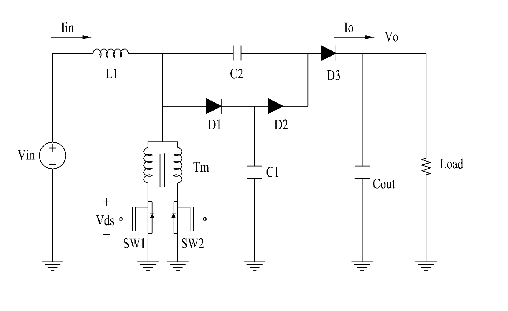
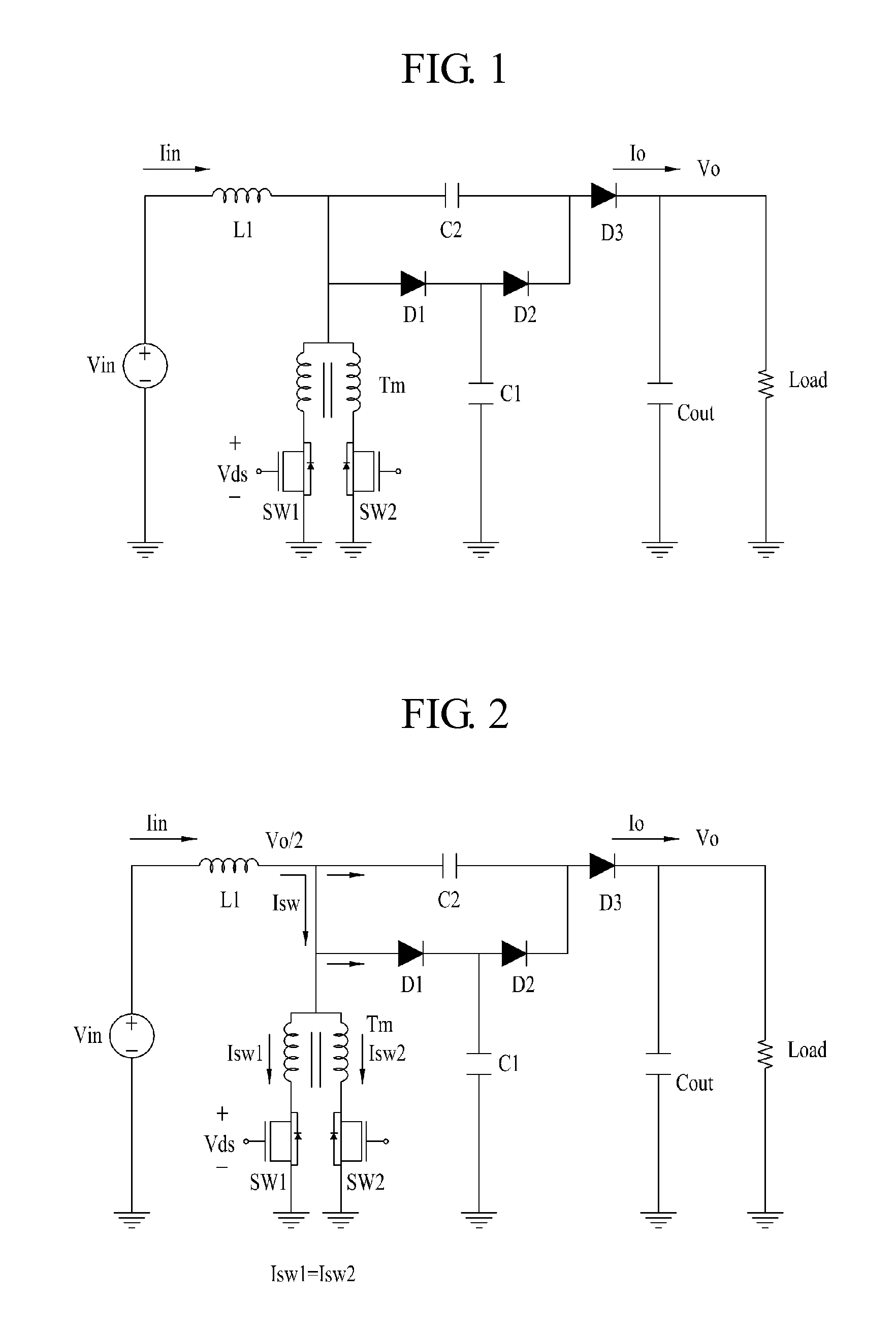
[0036]FIG. 1 is a circuit diagram showing a DC-DC boost converter circuit according to the present invention.

[0037]In the DC-DC boost converter circuit shown in FIG. 1, an inductor L1 and an output diode D3 are connected in series, and an output capacitor Cout is connected to an output port of the output diode D3 in parallel. The DC-DC boost converter circuit includes an output stabilization circuit in which first and second switching elements SW1 and SW2, a transformer Tm, a plurality of boost capacitors C1 and C2, and a plurality of diodes D1 and D2 are connected between the input-side inductor L1 and the output-side output diode D3 in series / parallel.

[0038]In detail, the DC-DC boost converter circuit is characterized in that the output stabilization circuit is included between the input-side inductor L1 and the output-side output diode D3 in the general DC-DC boost converter circuit including at least one inductor L1, the output diode D3 and the output capacitor Cout. The output ...

second embodiment

[0050]FIG. 7 is a circuit diagram showing a DC-DC boost converter circuit according to the present invention.

[0051]In the DC-DC boost converter circuit shown in FIG. 7, an inductor L1 and an output diode D3 are connected in series, and an output capacitor Cout is connected to an output port of the output diode D3 in parallel. The DC-DC boost converter circuit includes an output stabilization circuit in which first and second switching elements SW1 and SW2, a transformer Tm, a plurality of boost capacitors C1 and C2, and a plurality of diodes D1 and D2 are connected between the input-side inductor L1 and the output-side output diode D3 in series / in parallel.

[0052]The output stabilization circuit according to the second embodiment of the present invention includes the boost output capacitor C3 connected between the inductor L1 and the output diode D3 in series, the first and second stabilization diodes D1 and D2 which are connected to the boost output capacitor C3 in parallel and are ...


PUM


Abstract

Disclosed herein are a DC-DC boost converter circuit, which is capable of preventing power loss and stabilizing switching elements by implementing soft switching and improving efficiency by adding a charge pumping function, and a method for driving the same. The DC-DC boost converter circuit, in which an inductor and an output diode are connected in series and an output capacitor and a load are connected to an output port of the output diode in parallel, includes an output stabilization circuit in which first and second switching elements, a transformer, a plurality of boost capacitors, and a plurality of diodes are connected in series/parallel between the inductor and the output diode.

Description

[0001]This application claims the benefit of Korean Patent Application No. 10-2010-0056899, filed on Jun. 16, 2010, which is hereby incorporated by reference as if fully set forth herein.BACKGROUND OF THE INVENTION[0002]1. Field of the Invention[0003]The present invention relates to a high-efficiency power circuit, and more particularly, to a DC-DC boost converter circuit, which is capable of preventing power loss and stabilizing switching elements by implementing soft switching and improving efficiency by adding a charge pumping function, and a method for driving the same.[0004]2. Discussion of the Related Art[0005]A general power supply circuit includes a boost converter circuit for outputting a constant voltage by harmonics reduction and power factor improvement and an output voltage control circuit for receiving an output voltage from the boost converter circuit and outputting a desired output voltage.[0006]A DC-DC boost converter circuit includes an inductor, an output diode, a...

Claims


Application Information

Patent Timeline
Patent Type & Authority Applications(United States)
IPC IPC(8): H02M3/142
CPCH02M3/07Y02B70/1491H02M2001/346H02M3/158Y02B70/10H02M1/346H02M1/0095H02M1/0058
Inventor YUN, JAE-JUNGKIM, JUNG-JAEKANG, BONG-KOOHWANG, YOUNG-HOCHOE, HYUNG-JIN
Owner POSTECH ACAD IND FOUND
Why Eureka
Try Eureka