Method and Apparatus for Emulating Stream Clock Signal in Asynchronous Data Transmission

a technology of asynchronous data transmission and clock signal, applied in the field of data transmission, can solve the problem of not knowing the exact frequency in advan

Active Publication Date: 2011-12-22
ZHANG GUANSONG +2
View PDF2 Cites 9 Cited by
  • Summary
  • Abstract
  • Description
  • Claims
  • Application Information

AI Technical Summary

Benefits of technology

The system described above, wherein the emulated stream clock frequency is derived from adjusting a first stream clock frequency in the receiver module, wherein the first stream clock frequency is one selected from a group consisting of a selected frequency from the stream clock in the transmitter module, an average frequency from the stream clock in the transmitter module, and an estimated stream clock frequency, and wherein the first stream clock frequency is adjusted by: deriving a first metric value of at least one frame of the frame structure; setting a low limit metric value base on the first metric value; setting a high limit metric value base on the first metric value; comparing a second metric value of at least one other frame with said low limit and high limit metric values, and adjust the estimated stream clock frequency if the second metric value is outside of said low limit and high limit metric values.
In addition, the adjusting step of the above system further comprising: calculating a target step size of the adjusting step to satisfy a jitter performance of the system; controlling an adjustment step size to adjust the value of a control word derived in the estimated stream clock frequency generating step; reducing the adjustment step size at least one adjusting step until the adjustment step size is no larger than the target step size wherein the maximum number of adjustment steps is

Problems solved by technology

However, the proposed system has no knowledge of the exact frequency in advance.
The data stream may be single bit or multiple bits wide where the only limitation is that the aggregated bandwidth, i.e., the product of the data width and the clock frequency, does not exceed the bandwidth provided by the transmission link

Method used


Image

  • Method and Apparatus for Emulating Stream Clock Signal in Asynchronous Data Transmission
  • Method and Apparatus for Emulating Stream Clock Signal in Asynchronous Data Transmission
  • Method and Apparatus for Emulating Stream Clock Signal in Asynchronous Data Transmission

Examples


Embodiment Construction

The invention and its various embodiments can now be better understood by turning to the following detailed description of the preferred embodiments, which are presented as illustrated examples of the invention defined in the claims. It is expressly understood that the invention as defined by the claims may be broader than the illustrated embodiments described below.

The words used in this specification to describe the invention and its various embodiments are to be understood not only in the sense of their commonly defined meanings, but to include by special definition in this specification structure, material or acts beyond the scope of the commonly defined meanings. Thus if an element can be understood in the context of this specification as including more than one meaning, then its use in a claim must be understood as being generic to all possible meanings supported by the specification and by the word itself.

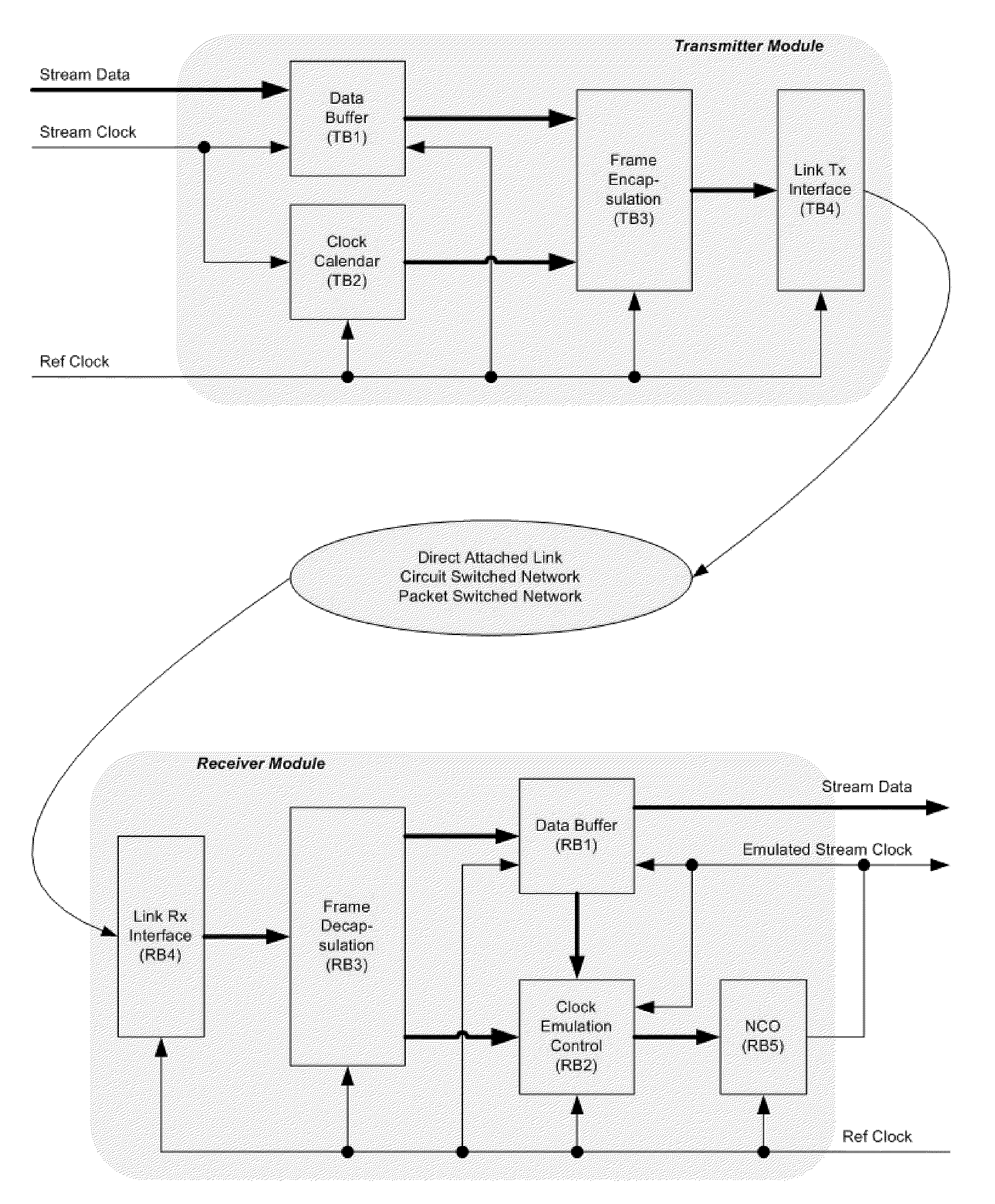
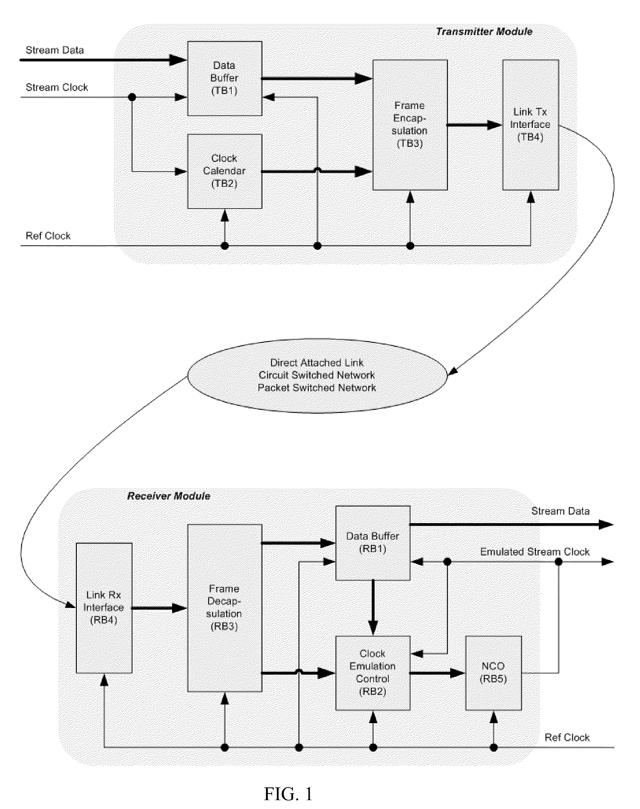
Referring now to FIG. 1, the system consists of a transmitter module in...


PUM


Abstract

A method and apparatus for emulating stream clock signal in asynchronous data transmission. The inventive subject matter proposes a system consisting of a transmitter module, a receiver module, and a link or network in between. A scheme to generate the emulated stream clock across a wide frequency range is also proposed with the property of controllable deviation from the original stream frequency to meet jitter requirement and fast frequency convergence (minimal number of converging steps). The scheme includes an optional first step to derive a frequency estimation of the stream clock and a second step of continuous adjusting the emulated clock frequency to keep the average frequency equals that of the original stream clock.

Description

CROSS-REFERENCE TO RELATED APPLICATIONSNot Applicable.STATEMENT REGARDING FEDERALLY SPONSORED RESEARCH OR DEVELOPMENTNot Applicable.THE NAMES OF THE PARTIES TO A JOINT RESEARCH AGREEMENTNot Applicable.BACKGROUND OF THE INVENTION(1) Field of the InventionThe field of the invention is data transmission.(2) Description of Related Art Including Information Disclosed Under 37 CFR 1.97 and 1.98Media extenders or media converters are commonplace in today's digital age, with such devices being incorporated in such industries as machine vision, broadcasting, or personal computer industries. Such devices are used to carry media streams, either video or voice, with constant data rates, from the stream data source, e.g., cameras, video cards, disc players, to the stream data sink, e.g., image capture cards, display panels, image processors, etc. The purpose of using such devices includes long distance transmission, networked switching, intermediate data processing, etc, where the original media...

Claims


Application Information

Patent Timeline
Patent Type & Authority Applications(United States)
IPC IPC(8): H04L7/00
CPCH04J3/0632
Inventor ZHANG, GUANSONGYANG, TSUNG-YIZHANG, CATHY
Owner ZHANG GUANSONG
Why Eureka
Try Eureka