Analyzer of ultrasonic flaw detection image

an ultrasonic flaw detection and ultrasonic technology, applied in the field of ultrasonic flaw detection imaging, can solve the problems of single flaw detection image being insufficient to determine accurately, finding a defect, serious accident, etc., and achieve the effect of eliminating the omission of defect detection and saving labor and time for inspection

Active Publication Date: 2011-12-22
MITSUBISHI HEAVY IND LTD
View PDF1 Cites 9 Cited by
  • Summary
  • Abstract
  • Description
  • Claims
  • Application Information

AI Technical Summary

Benefits of technology

[0082]According to the present invention, in observing an ultrasonic flaw detection image to detect a defect, optimum images are displayed sequentially in an optimum arrangement pattern, in an optimum display range, and with an optimum contrast, in accordance with the defect to be inspected for. This saves an operator from having to manually select the image or change the arrangement pattern, the display range or the contrast, and can result in savings in labor and time for inspection.
[0083]Moreover, the defect can be detected accurately regardless of the degree of mastery of the operator, and an omission of defect detection is eliminated.

Problems solved by technology

In the aircraft, damage to the wing poses a danger directly leading to a serious accident.
Thus, it is very important to perform operations for maintenance and checkup, thereby finding a defect.
Thus, a single flaw detection image may be insufficient to determine accurately whether there is a defect or not.
However, it takes too much time to analyze all of flaw detection waveforms by a flaw detection waveform signal obtained by this test.

Method used


Image

  • Analyzer of ultrasonic flaw detection image
  • Analyzer of ultrasonic flaw detection image
  • Analyzer of ultrasonic flaw detection image

Examples


embodiment 1

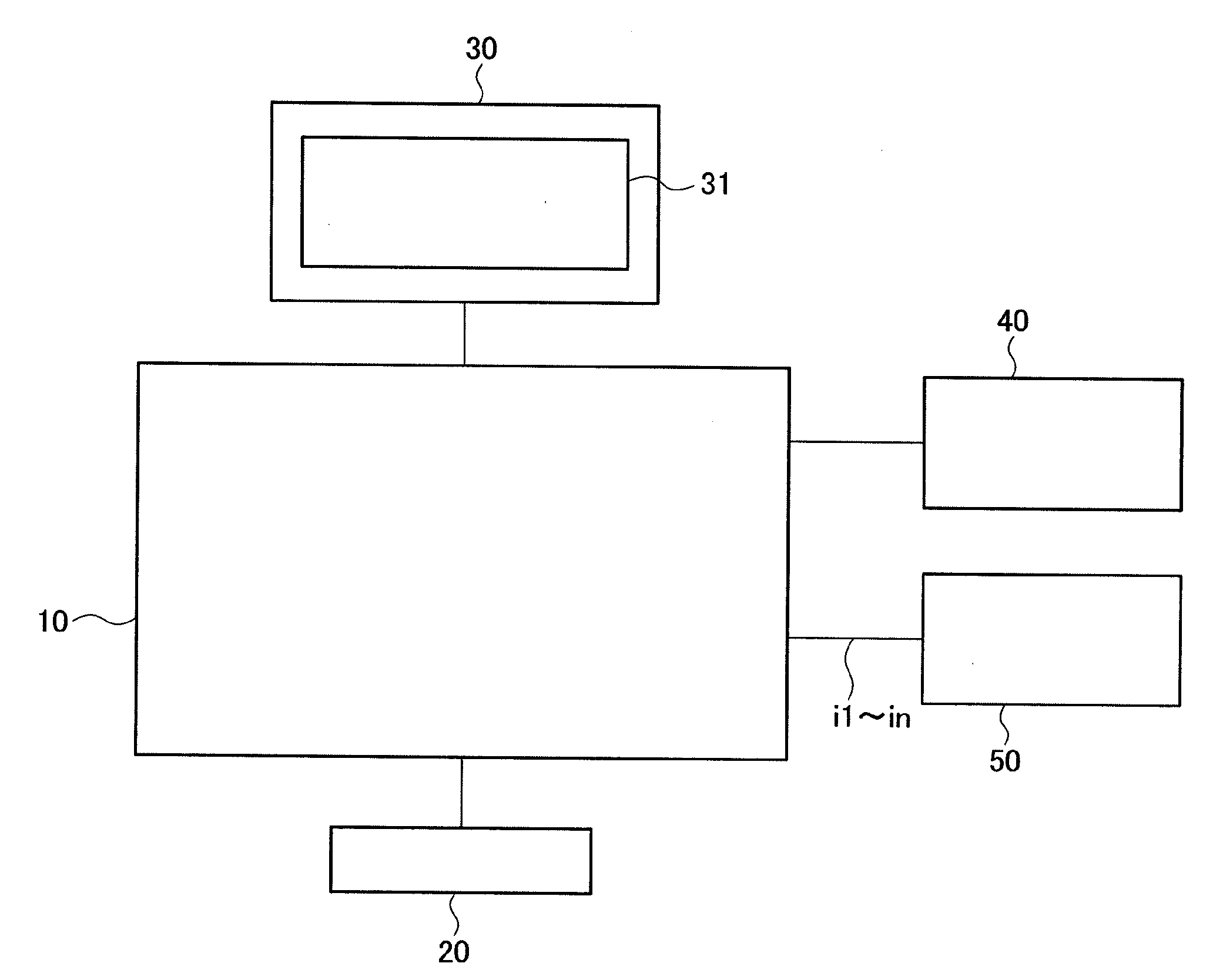
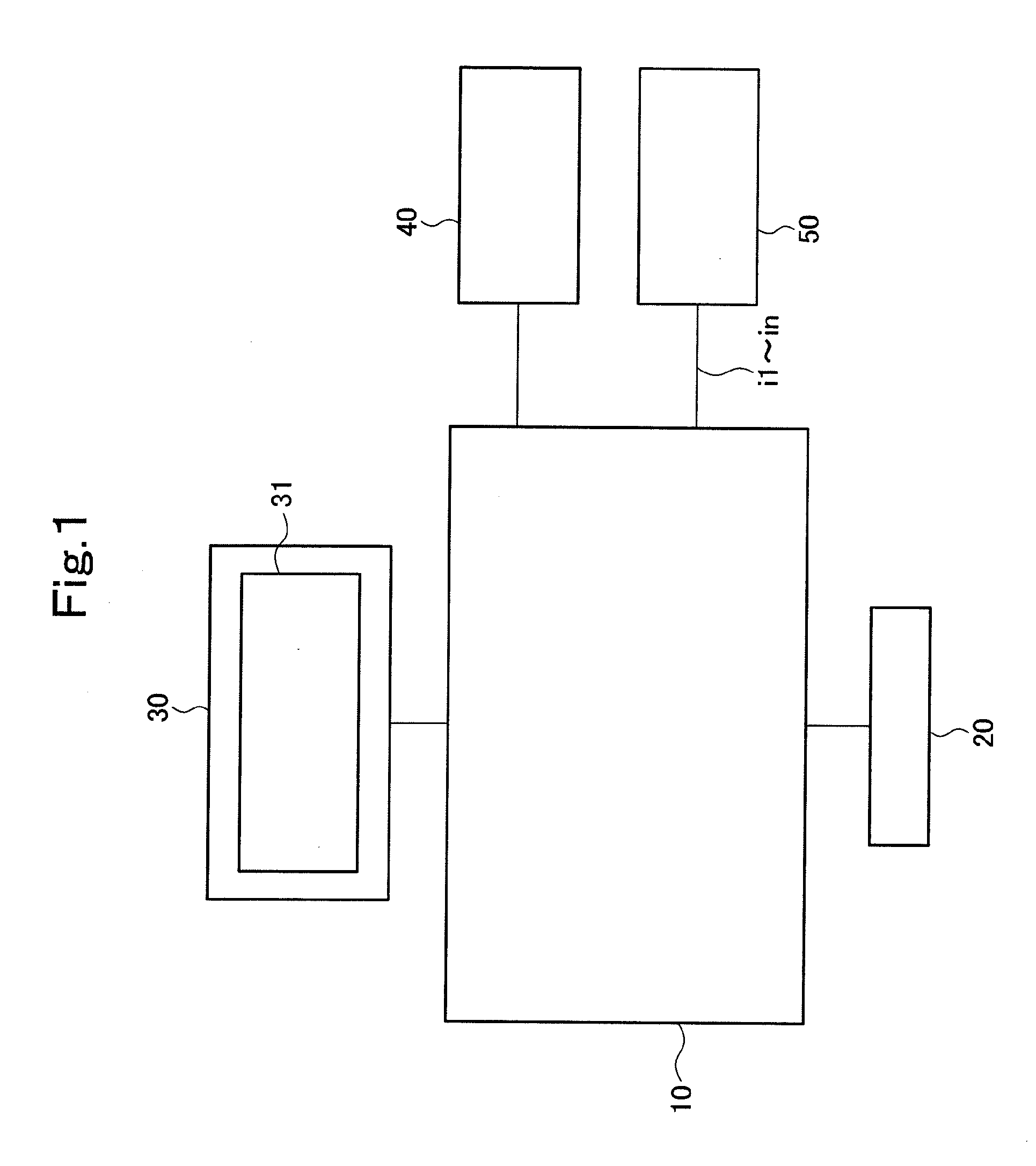
[0106]FIG. 1 is a block diagram showing an analytical apparatus for an ultrasonic flaw detection image according to Embodiment 1 of the present invention. This analytical apparatus for an ultrasonic flaw detection image is composed of a flaw detection image analyzer 10, an input device 20, an image display device 30, a flaw detection condition database division 40, and a flaw detection image signal database division 50.

[0107]The flaw detection image signal database division 50 has a plurality of flaw detection image signals i1 to in stored beforehand. These plural flaw detection image signals i1 to in are obtained by signal transformation of a flaw detection waveform signal, which has been acquired during the movement of an ultrasonic probe along a flaw detection path set on the main wing of an aircraft, by a plurality of different signal transformation techniques (a TOF image signal transformation technique, an AMP image signal transformation technique, and signal transformation te...

embodiment 2

[0147]FIG. 4 is a block diagram showing an analytical apparatus for an ultrasonic flaw detection image according to Embodiment 2 of the present invention. This analytical apparatus for an ultrasonic flaw detection image is composed of a flaw detection image analyzer 10, an input device 20, an image display device 30, a flaw detection condition database division 40, a flaw detection image signal database division 50, and a three-dimensional CAD model division 60.

[0148]The three-dimensional CAD model division 60 has in storage various data necessary for designing an object to be inspected (e.g., the main wing of an aircraft), for example, design data, such as plate thickness, shape, material, dimensions, and structure.

[0149]The flaw detection image signal database division 50 has a plurality of flaw detection image signals i1 to in stored beforehand. These plural flaw detection image signals i1 to in are obtained by signal transformation of a flaw detection waveform signal, which has ...

embodiment 3

[0196]FIG. 8 is a block diagram showing an analytical apparatus for an ultrasonic flaw detection image according to Embodiment 3 of the present invention. This analytical apparatus for an ultrasonic flaw detection image is composed of a flaw detection image analyzer 10, an input device 20, an image display device 30, a flaw detection condition database division 40, a flaw detection image signal database division 50, a three-dimensional CAD model division 60, and a plate thickness measuring device 70.

[0197]The plate thickness measuring device 70 actually measures the plate thickness of an object to be inspected (for example, the main wing of an aircraft), and outputs its measured value (plate thickness).

[0198]The three-dimensional CAD model division 60 has in storage various data necessary for designing the object to be inspected (e.g., the main wing of an aircraft), for example, design data, such as plate thickness, shape, material, dimensions, and structure.

[0199]The flaw detection...


PUM


Abstract

A flaw detection image analyzer (10) takes in an inspection procedure command stored in a flaw detection condition database (40), takes in a flaw detection image signal corresponding to a flaw detection image indicated by the taken inspection procedure command from a database (50) for flaw detection image signal, and displays the flaw detection image based on the flaw detection image signal on a display (30), with a display range and a contrast indicated by the inspection procedure command in an arrangement pattern of image indicated by the inspection procedure command. Consequently, optimum images can be displayed sequentially with optimum arrangement pattern, optimum display range and contrast according to a flaw to be inspected when a flaw is detected by observing an ultrasonic flaw detection image.

Description

TECHNICAL FIELD[0001]This invention relates to an analyzer or analytical apparatus for an ultrasonic flaw detection image, which is designed to be capable of reducing labor and time for conducting an inspection for a defect and also capable of detecting the defect accurately regardless of the degree of mastery.BACKGROUND ART[0002]The main wing of an aircraft has so far been produced using an aluminum alloy or a titanium alloy, but recently, has used a carbon fiber-reinforced plastic (CFRP) comprising a combination of carbon fibers and resin.[0003]In the aircraft, damage to the wing poses a danger directly leading to a serious accident. Thus, it is very important to perform operations for maintenance and checkup, thereby finding a defect.[0004]Defects occurring in the wing of the aircraft include a flaw, foreign matter, a peel, and so on. As a nondestructive examination for detecting these defects, an ultrasonic flaw detection test or inspection is adopted.[0005]A general technique f...

Claims


Application Information

Patent Timeline
Patent Type & Authority Applications(United States)
IPC IPC(8): G06K9/00
CPCG01N29/069G01N29/4427G06T7/0008G06T7/001G01N2291/2694
Inventor KITAGAWA, TOMOAKITAKEMOTO, HIROSHI
Owner MITSUBISHI HEAVY IND LTD
Why Eureka
Try Eureka