
Trajectory simulation system utilizing dynamic target feedback that provides target position and movement data

a trajectory simulation and target feedback technology, applied in the field of tactical engagement simulation systems, can solve problems such as line-of-sight delay, flawed approach, and inability to represent a real-world situation

Inactive Publication Date: 2011-12-22
LOCKHEED MARTIN CORP
View PDF4 Cites 52 Cited by
  • Summary
  • Abstract
  • Description
  • Claims
  • Application Information

AI Technical Summary

Benefits of technology

[0009]Another aspect of the present disclosure is for a global position system (GPS) augmented trajectory system (GATS), which is a discrete system able to be mounted on a projectile weapon barrel of a weapon system. The GATS system can include a vertical scanning laser, a directional radio frequency (RF) transceiver, a global position system (GPS) component, and a set of computer program products. The vertical scanning laser can be for emitting Multiple Integrated Laser Engagement System (MILES) compliant optical emissions. The directional radio frequency (RF) transceiver can be for emitting radio frequency signals containing digitally encoded data and for receiving radio frequency signals containing digitally encoded data. The global position system (GPS) component can be for determining a geographic position of the GATS within a physical combat simulation environment. When executed, the computer program products can utilize the vertical scanning laser to continuously scan along an axis of the projectile weapon barrel. The GATS can receive, via the directional radio frequency (RF) transmitter, feedback encoded within RF signals from potential targets which sensed the continuous scans from the vertical scanning laser and provided the feedback in response. The computer program products can perform pre-fire event computations that utilize the feedback for determining potential target positions relative to the GATS. The computer program products, when executed, can adjust an aim point of the vertical scanning laser to a position that a potential target must be at in order to be affected by a fire event. Then the computer program products can cause the vertical scanning laser, which has been adjusted aim point, to fire.
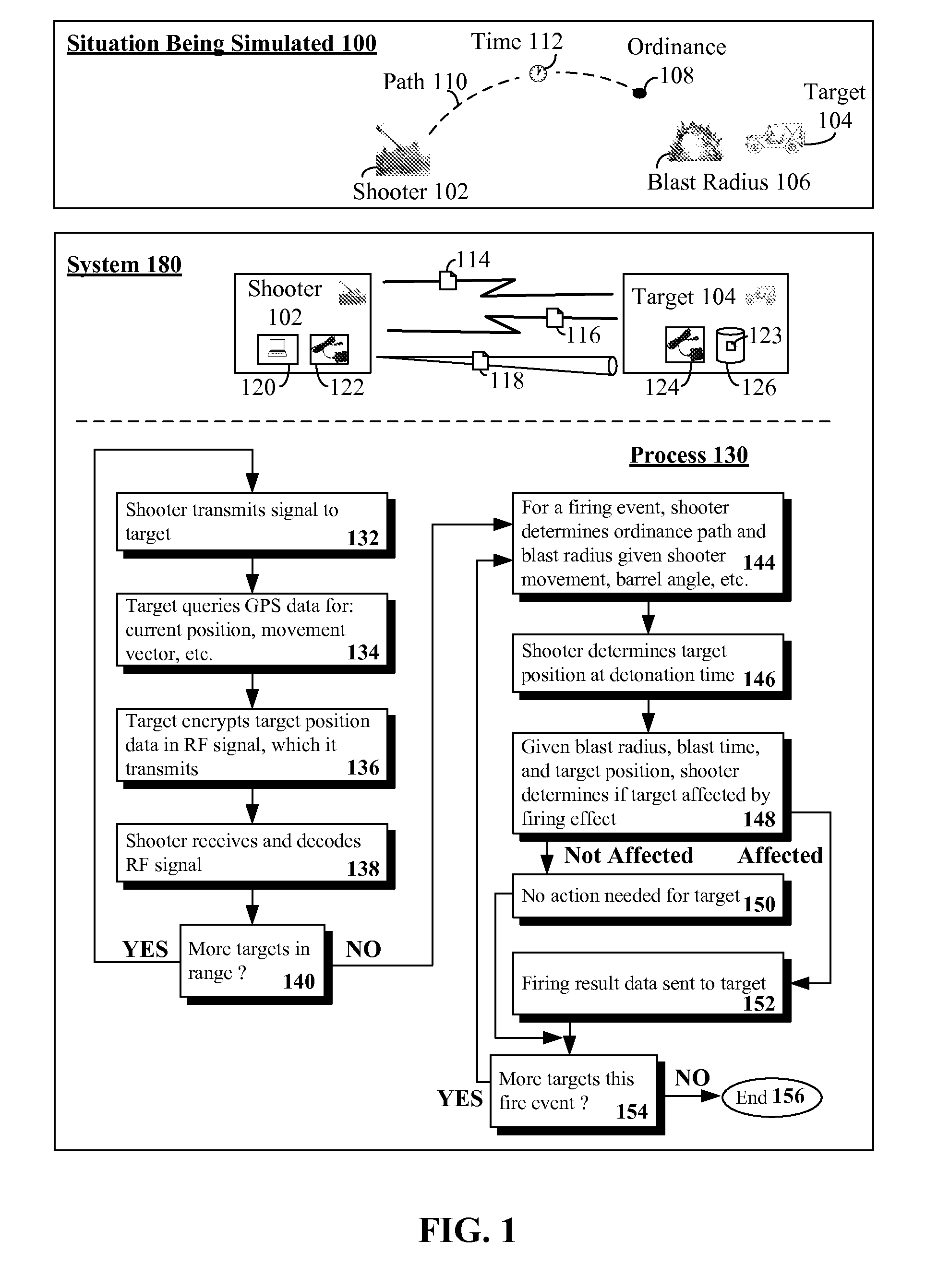
[0011]Another aspect of the present disclosure includes a tactical engagement simulation (TES) method. The method can receive fire result data from a shooter in a physical combat simulation environment. The fire result data can include an ordinance blast radius and a detonation time for a simulated kinetic weapon of the shooter firing a simulated ordinance. No actual projectile is physically conveyed from the shooter to a target within the physical combat simulation environment. The fire result data can be received before the detonation time. At the detonation time, the target can determine its geographic position within the physical combat simulation environment using a position determination component, which is a hardware component of the target. When the determined geographic position the target is outside the ordinance blast radius at the detonation time, the target can take no action related to the fire result data. When the determined geographic position of the target is inside the ordinance blast radius at the detonation time, the target can compute an effect of being within the blast radius of the simulated ordinance. Then the target can selectively adjust a simulation state of target equipment based on the computed effect.

Problems solved by technology

This approach is flawed in that it is not representative of a real-world situation.
The line-of-sight delay for traditional TES systems is an artificial constraint causing an operator of a weapon system to not be permitted to select a new target immediately after firing.
Failure to maintain the sight picture (altering line-of-sight) of the fired weapon during this delay period produces inaccurate simulation results.
Another possible inaccuracy is that compensation mechanisms implemented to compensate for the delay period are overly generous, which result in false positive hits.

Method used


Image

  • Trajectory simulation system utilizing dynamic target feedback that provides target position and movement data
  • Trajectory simulation system utilizing dynamic target feedback that provides target position and movement data
  • Trajectory simulation system utilizing dynamic target feedback that provides target position and movement data

Examples


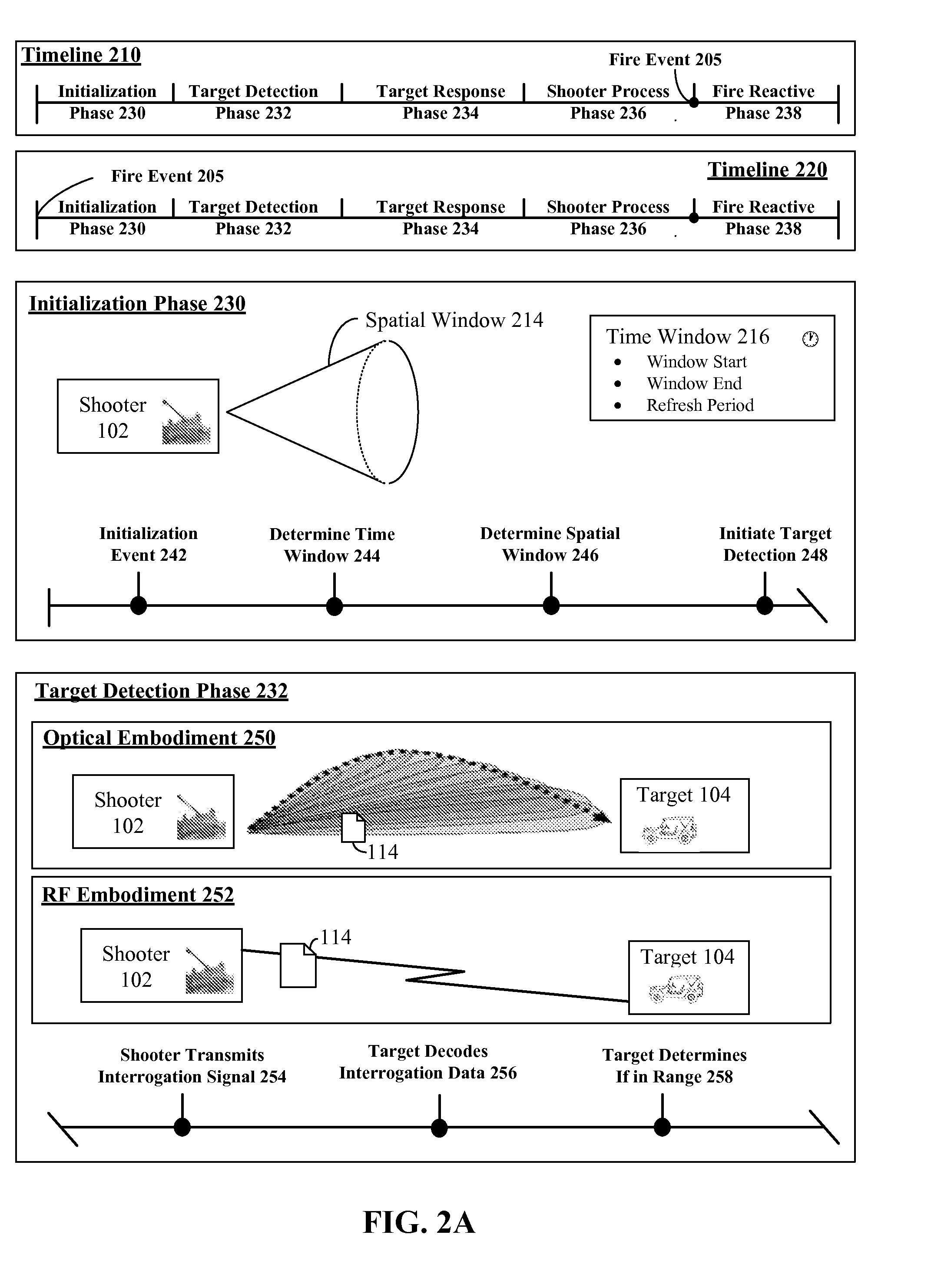
embodiment 250

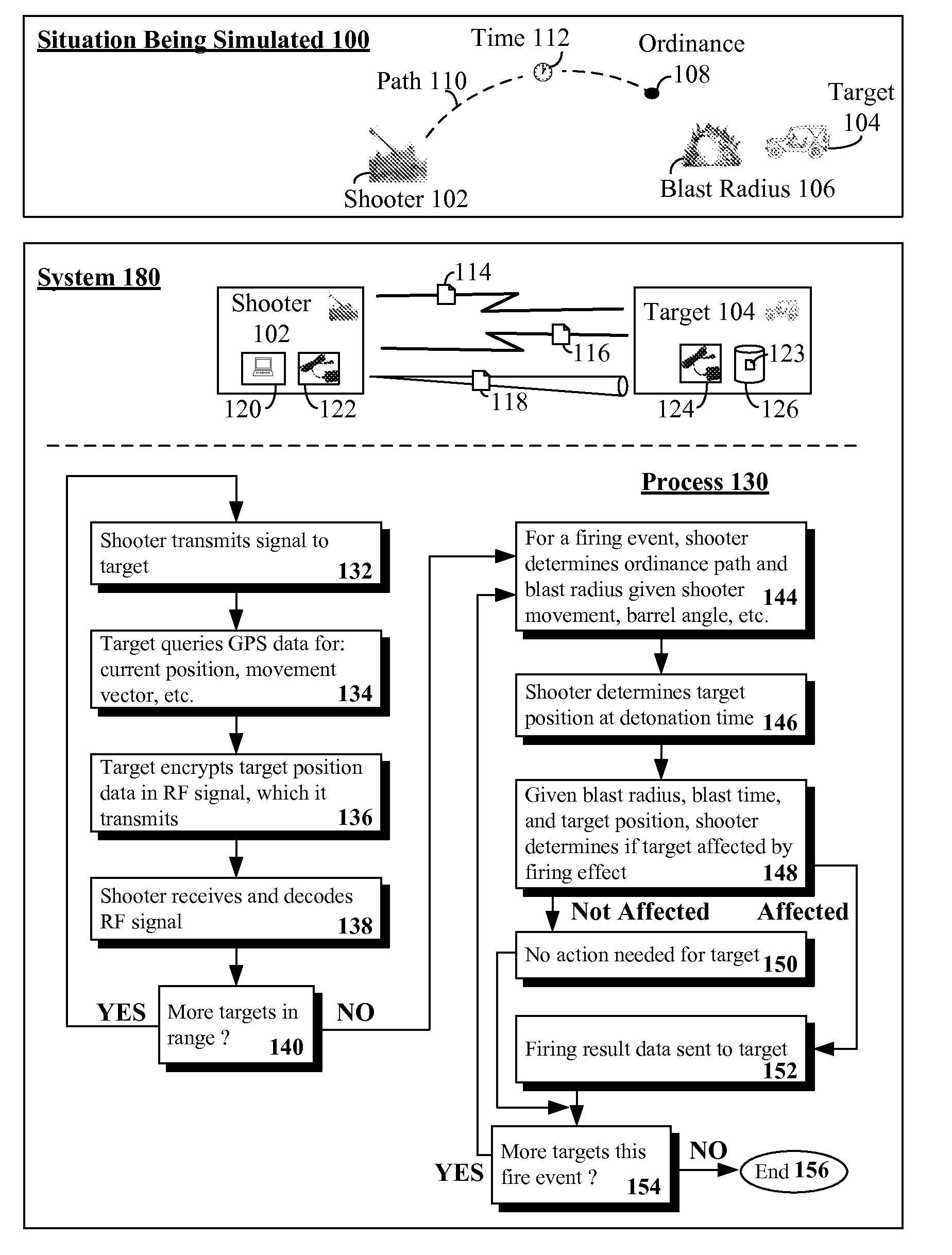
[0046]In target response phase 234, the target 104 can query recently obtained GPS data 260. For example, a target's GPS component 124 can record a recent history 123 in a memory 126. This GPS data 123 can be optionally processed 262 by the target and encoded 264 in a radio frequency signal, which the target transmits 266. The encoded data 116 can include, for example, a GPS position of the target 104, a velocity vector of the target 104, a vertical scan number (of a sensed optical signal—assuming embodiment 250), and other such data.

[0047]In the shooter process phase 236, the shooter 102 can receive and decode the response 116. The shooter 102 can also query 268 its own GPS component 122. From the shooter's GPS data, shooter 102 movement can be determined. Ordinance path, blast radius, detonation time (given shooter 102 movement) and the like can be determined 270 for a firing event. Further, a target position at detonation time 272 can be determined (from the target's GPS data and...

embodiment 257

[0048]In the fire reactive phase 238, the shooter 102 can convey fire response data 118 to the target 104. In one embodiment 257, the shooter 102 can use a laser to convey a kill command to the target 104. This can require an adjustment 276 in a laser aim point to the target position. The adjustment 276 can be based on shooter 102 calculations that utilize target 104 provided GPS data (from feedback 116). For example, target 104 distance can be determined from the feedback (116) provided data, current target position for laser aim point adjustment can be based on target vehicle vector (movement) calculations, etc.

[0049]In one embodiment, adjustments to the laser aim point 276 can occur in advance of (and / or independent of) a fire event. These laser aim point adjustments can also occur independent of weapon barrel movement.

[0050]In embodiment 259, fire response data 118 can be encoded and conveyed from the shooter 102 to the target 104 over a RF transmission. The response data 118 ca...


PUM


Abstract

A target in a physical environment can be interrogated. Feedback can be received from the target that is encoded within a radio frequency signal. The feedback can include position and movement data of the target. Adjustments can be calculated for a simulated kinetic projectile traveling to the target. The adjustments can account for target movement, kinetic projectile travel time, and travel path to the target. A distance from a point of origin of the simulated kinetic projectile to the target and movement of the target relative to the point of origin can be determined utilizing the feedback. A result signal can be conveyed that includes result data. The result data can include all information necessary for the target to react to the simulated kinetic projectile.

Description

STATEMENT REGARDING FEDERALLY SPONSORED RESEARCH OR DEVELOPMENT[0001]This invention was made with U.S. Government support under Contract No. N61339-01-D-0717-0003 awarded by the U.S. Navy. The Government has certain rights in the invention including a paid-up license and the right in limited circumstances to require the patent owner to license others on reasonable terms as provided by for the terms of Contract No. N61339-01-D-0717-0003 awarded by the U.S. Navy.BACKGROUND[0002]The disclosure relates to the field of tactical engagement simulation systems (TES) and, more particularly, to target position augmented trajectory simulation systems that utilize dynamic target feedback.[0003]TES is a training system for using weapons and conducting force-on-force exercises. In a TES simulation, laser transmitters are often used instead of bullets, larger rounds, or shorter-range guided weapons such as anti-tank missiles. These laser transmitters are mounted on the weapon and aligned with the ...

Claims


Application Information

Patent Timeline
IPC IPC(8): F41G3/26
CPCF41G3/26F41G3/2666F41G3/2655F41G3/265
Inventor PRESTON, STEVENKAPROCKI, EDWARD S.PENNER, TOM
Owner LOCKHEED MARTIN CORP
Learn More