Control device for vehicular power transmitting apparatus

a control device and transmission device technology, applied in the direction of electric propulsion mounting, dynamo-electric gear control, gear control, etc., can solve the problems of increasing the synchronization time of the transmission, slowing the response during the shifting, and limiting the synchronization time, so as to reduce the transmission time and reduce the transmission time. , the effect of reducing the transmission tim

Active Publication Date: 2011-12-22
TOYOTA JIDOSHA KK +1
View PDF3 Cites 11 Cited by
  • Summary
  • Abstract
  • Description
  • Claims
  • Application Information

AI Technical Summary

Benefits of technology

[0011]The above structure allows an appropriate shifting to be executed depending on torque of the electric motor, resulting in the compatible effects of quickened response and the suppressed shifting shock in the kickdown shifting. For instance, when the kickdown shifting is performed by depressing an accelerator pedal under a state in which the input torque applied to the transmission is smaller, the rotation-synchronization control by the electric motor is performed. This achieves the rotation synchronization immediately, resulting in the quickened shifting response. Further, during the execution of the rotation-synchronization control by the electric motor, interruption of the power transmitting in the transmission may cause the fall of the drive force. However, owing to the smaller input torque applied to the transmission, the shifting shock associating therewith is suppressed. Furthermore, when the kickdown shifting is performed by depressing the accelerator pedal under the state in which the input torque applied to the transmission is larger, the rotation-synchronization control is performed by the hydraulic pressure control of the transmission. This can output the drive force continuously, then the fall of the drive force can be avoided, and the shifting shock can be suppressed. Thus, by switching the methods of rotation-synchronization controls of the transmission depending on the input torque applied to the transmission at the beginning of the shifting, compatible effects of the quickened shifting response and suppressed shifting shock can be obtained.
[0012]In the control device for a vehicular power transmitting apparatus of the second aspect, the synchronizing control method is switched to the rotation-synchronization control by the hydraulic pressure control of the transmission when the input t...

Problems solved by technology

This increases a synchronization time of the transmission, slowing the response during the shifting.
Thus, there is a limit in shortening the synchronization time.
On the contrary, executing the rotation-synchronization control by the electric motor with taking priority to the quick or quickened shifting response can shorten the ...

Method used


Image

  • Control device for vehicular power transmitting apparatus
  • Control device for vehicular power transmitting apparatus
  • Control device for vehicular power transmitting apparatus

Examples


embodiment 1

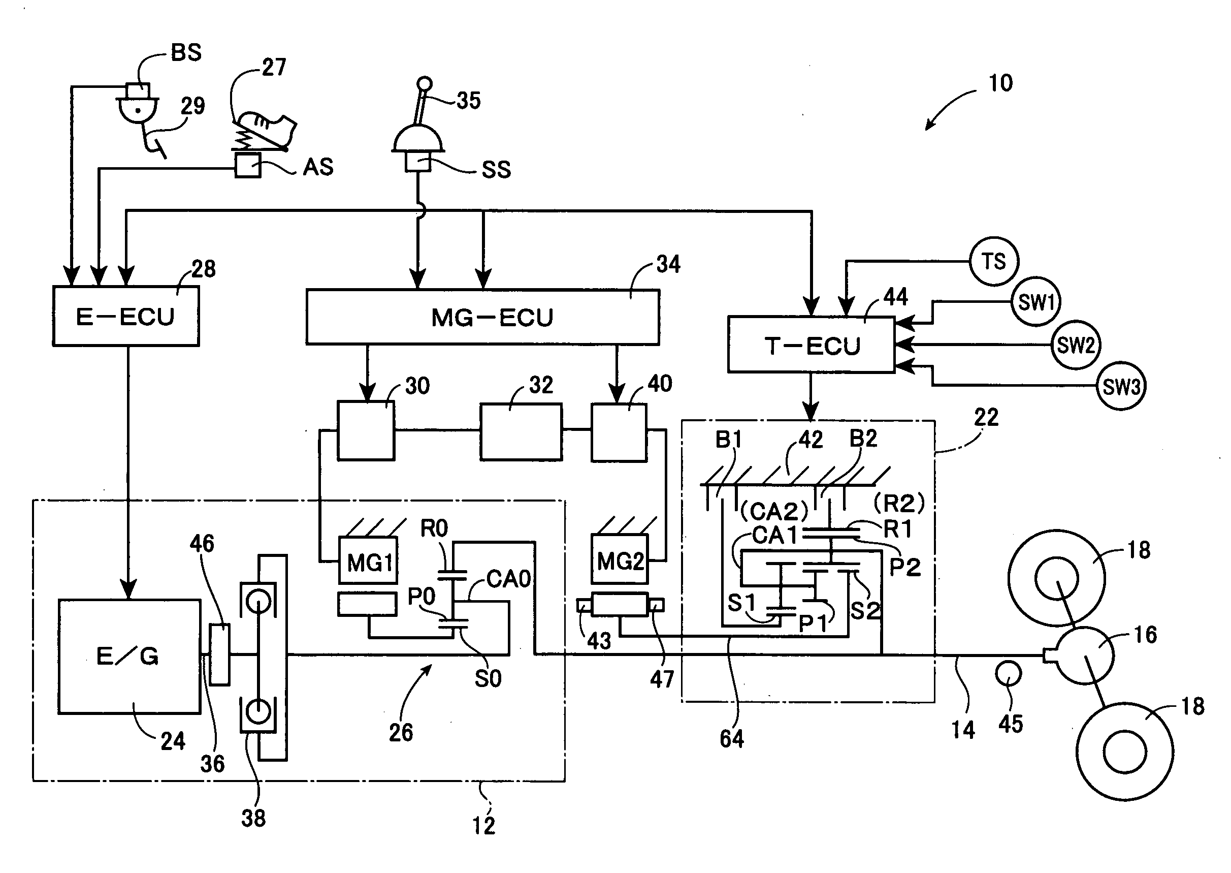
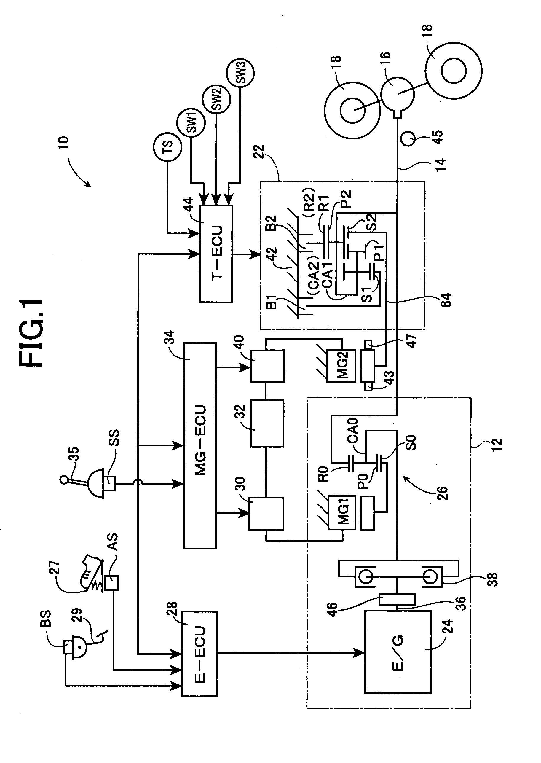
[0030]Referring to the schematic view of FIG. 1 for explaining a hybrid type vehicular power transmitting apparatus 10 to which the present invention is applicable, the vehicular power transmitting apparatus 10 is arranged such that a torque of a main drive power source functioning as a first drive power source 12 is transmitted to a wheel-side output shaft (hereinafter referred to “output shaft”) 14 functioning as an output member, and then it is transmitted to a pair of right and left drive wheels 18 through a differential gear device 16. The vehicular power transmitting apparatus 10 is provided with, as a second drive power source, a second electric motor MG2 which is operable to selectively perform a torque generating operation to generate a vehicle drive force and a regenerative operation to recover a kinetic energy. This second electric motor MG2 is connected to the output shaft 14 through an automatic transmission 22 (corresponding to “transmission” in the present invention)....

embodiment 2

[0083]FIG. 9 is a flowchart related to an another embodiment for illustrating a major part of control operations executed by the electronic control devices (28, 34 and 44), i.e., a sequence of control operations available to provide compatible effects of a quickening in response and a suppression in shock in the kickdown shifting. Also, steps SA1 to SA5 are identical to those of the embodiment 1 set forth above, and hence, description thereof is omitted.

[0084]Here, motor-synchronization control determining means 72 additionally incorporated in the present embodiment 2 as shown in FIG. 4, serves to determine as to whether the control method executed in the rotation-synchronization control belongs to the rotation-synchronization control by the second electric motor MG2, in the downshifting of the automatic transmission 22. Such a determination is made in response to a control method switching command or the like delivered from for instance the synchronization-control-method switching ...

embodiment 3

[0088]FIG. 10 is a skeleton view showing a structure of a vehicular power transmitting apparatus (hereinafter referred to merely as a “power transmitting apparatus 100”) of a still another embodiment 3 according to the present invention. In FIG. 10, the power transmitting apparatus 100 includes a crankshaft 36 acting as an input rotation member; a planetary gear unit 26 directly connected to the crankshaft 26 or indirectly connected thereto via a pulsation absorbing damper (vibration damping device) (not shown) acting as a power distributing mechanism; an automatic transmission 108 (transmission) connected to the planetary gear unit 26 in series via a transfer member 106 in a power transmitting path between the planetary gear unit 26 and drive wheels 18 and acting as a power transmitting section; and an output shaft 14 connected to the automatic transmission 108 in series to act as an output rotation member. These are disposed on a common axis in a housing 42 acting as a non-rotary ...


PUM


Abstract

It is provided a control device for a vehicular power transmitting apparatus provided with a transmission disposed in a power transmitting path between an electric motor and drive wheels, the control device switching a synchronizing control method of the transmission in a kickdown shifting performed in the transmission to either one of a rotation-synchronization control by a hydraulic pressure control of the transmission and a rotation-synchronization control by the electric motor, depending on an input torque applied to the transmission at the beginning of the shifting.

Description

FIELD OF THE INVENTION[0001]This invention relates to a control device for a vehicular power transmitting apparatus including a transmission disposed in a power transmitting path between an electric motor and drive wheels, and more particularly, to a technology of quickening a response and suppressing a shock in a kickdown shifting.DESCRIPTION OF THE RELATED ART[0002]There has heretofore been known a vehicular power transmitting apparatus of a hybrid type including a transmission disposed in a power transmitting path between an electric motor and drive wheels. In such a vehicular power transmitting apparatus, a drive force (torque) output from the electric motor can be amplified with the transmission and transmitted to the drive wheels. As the transmission for example a hydraulic type automatic transmission controlled with a hydraulic pressure may be used, in which a shifting is suitably performed depending on a running state of a vehicle. For instance, the transmission is shifted t...

Claims


Application Information

Patent Timeline
IPC IPC(8): B60W10/10B60W10/08B60K6/445B60K6/547B60W20/00F16H59/14F16H61/04F16H61/68F16H61/684F16H61/686F16H63/40F16H63/50
CPCB60K1/02Y10T477/26B60K6/445B60K6/547B60L2240/421B60L2240/486B60W10/06B60W10/08B60W10/115B60W20/00B60W30/18027B60W30/19B60W2510/1025B60W2540/10B60W2540/12B60W2540/16B60W2710/0666B60W2710/081F16H3/727F16H59/14F16H59/20F16H61/0437F16H61/061F16H2037/0873F16H2061/0422Y02T10/6239Y02T10/6286Y02T10/642F16H2059/147Y10T477/33B60K6/365Y02T10/62Y02T10/64B60W20/30B60W10/10
Inventor ITO, MASATOSHIUEJIMA, TAIYOOYAMA, SHUNSUKENOMURA, MASAKINOMURA, TOMOKAZU
Owner TOYOTA JIDOSHA KK
Why Eureka
Try Eureka