Microfluidic device with chemical lysis section

a microfluidic and chemical lysis technology, applied in the field of diagnostic devices, can solve the problems of slow growth of this type of testing in the clinical laboratory, reduced sensitivity, and high degree of non-specific binding, and achieve the effects of simple system manufacturing procedures, low system component count, and simple assay procedures

Inactive Publication Date: 2011-12-22
GENEASYS
View PDF5 Cites 0 Cited by
  • Summary
  • Abstract
  • Description
  • Claims
  • Application Information

AI Technical Summary

Benefits of technology

[0091]The easily usable, mass-producible, and inexpensive microfluidic device accepts a biochemical sample, uses a chemical lysis subunit for lysing cells or cell organelles, and processes the lysates.
[0092]The lysing process extracts analytical and diagnostic targets from cells

Problems solved by technology

Insufficient stringency can result in a high degree of nonspecific binding.
Excessive stringency can lead to a failure of appropriate binding, which results in diminished sensitivity.
Despite the advantages that molecular diagnostic tests offer, the growth of this type of testing in the clinical laboratory has been slower than expected and remains a minor part of the practice of laboratory medicine.
This is primarily due to the complexity and costs associated with nucleic acid testing compared with tests based

Method used


Image

  • Microfluidic device with chemical lysis section
  • Microfluidic device with chemical lysis section
  • Microfluidic device with chemical lysis section

Examples


Embodiment Construction

Overview

[0233]This overview identifies the main components of a molecular diagnostic system that incorporates embodiments of the present invention. Comprehensive details of the system architecture and operation are set out later in the specification.

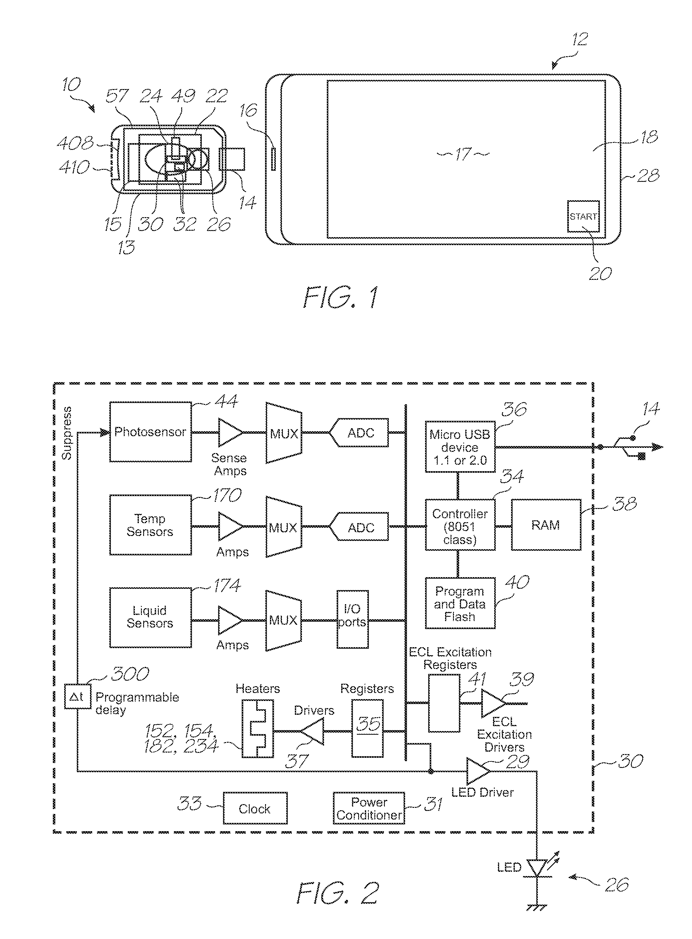
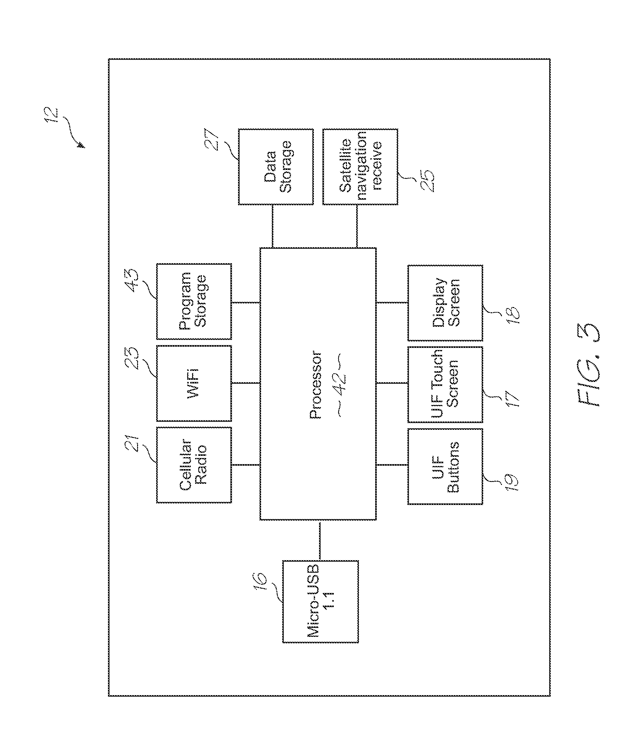
[0234]Referring to FIGS. 1, 2, 3, 104 and 105, the system has the following top level components:

[0235]Test modules 10 and 11 are the size of a typical USB memory key and very cheap to produce. Test modules 10 and 11 each contain a microfluidic device, typically in the form of a lab-on-a-chip (LOC) device 30 preloaded with reagents and typically more than 1000 probes for the molecular diagnostic assay (see FIGS. 1 and 104). Test module 10 schematically shown in FIG. 1 uses a fluorescence-based detection technique to identify target molecules, while test module 11 in FIG. 104 uses an electrochemiluminescence-based detection technique. The LOC device 30 has an integrated photosensor 44 for fluorescence or electrochemiluminescence detection...


PUM

PropertyMeasurementUnit
Areaaaaaaaaaaa
Areaaaaaaaaaaa
Areaaaaaaaaaaa

Abstract

A microfluidic device for lysing cells in a fluid, the microfluidic device having an inlet for receiving a fluid containing cells, a lysis reagent reservoir containing a lysis reagent and having an outlet valve, and, a lysis section in fluid communication with the inlet for holding the fluid during lysis of the cells, wherein, the outlet valve is upstream of the lysis section and configured to open as the fluid flows into the lysis section thereby adding the lysis reagent to the fluid.

Description

FIELD OF THE INVENTION[0001]The present invention relates to diagnostic devices that use microsystems technologies (MST). In particular, the invention relates to microfluidic and biochemical processing and analysis for molecular diagnostics.[0002]CO-PENDING APPLICATIONS[0003]The following applications have been filed by the Applicant which relate to the present application:GBS001USGBS002USGBS003USGBS005USGBS006USGSR001USGSR002USGAS001USGAS002USGAS003USGAS004USGAS006USGAS007USGAS008USGAS009USGAS010USGAS012USGAS013USGAS014USGAS015USGAS016USGAS017USGAS018USGAS019USGAS020USGAS021USGAS022USGAS023USGAS024USGAS025USGAS026USGAS027USGAS028USGAS030USGAS031USGAS032USGAS033USGAS034USGAS035USGAS036USGAS037USGAS038USGAS039USGAS040USGAS041USGAS042USGAS043USGAS044USGAS045USGAS046USGAS047USGAS048USGAS049USGAS050USGAS054USGAS055USGAS056USGAS057USGAS058USGAS059USGAS060USGAS061USGAS062USGAS063USGAS065USGAS066USGAS067USGAS068USGAS069USGAS070USGAS080USGAS081USGAS082USGAS083USGAS084USGAS085USGAS086USGAS08...

Claims


Application Information

Patent Timeline
IPC IPC(8): C40B60/12C12M1/00C12M1/38C12M1/33
CPCB01L3/5027Y10T436/25B01L3/502738B01L7/52B01L2200/10B01L2300/023B01L2300/024B01L2300/0636B01L2300/0654B01L2300/0883B01L2300/10B01L2300/1827B01L2400/0406B01L2400/0633B01L2400/0677B01L2400/0688F16K99/003F16K99/0036G01N27/223C12Q1/68Y10T436/107497Y10T436/173845Y10T436/143333Y10T436/11Y10T436/145555Y10T436/203332Y10T436/25375B01L3/502707Y10T137/0352Y10T137/0391Y10T137/1044Y10T137/206Y10T137/2076Y10T137/2202Y02A90/10
Inventor SILVERBROOK, KIAAZIMI, MEHDIFACER, GEOFFREY RICHARD
Owner GENEASYS
Why Eureka
Try Eureka