Supercharge Your Innovation With Domain-Expert AI Agents!

Isolated Counter-Flow Air Heat Exchanging Device with Vertical Structure

a counter-flow air and heat exchange technology, which is applied in indirect heat exchangers, lighting and heating apparatus, heating types, etc., can solve the problems of large energy consumption of air conditioning equipment, large energy source problem, and increase in the number of used conventional air conditioning equipment, etc., to achieve large heat exchange performance, small floor area, and large capacity

Inactive Publication Date: 2011-12-29
TONLIER ENERGY TECHBEIJINGCO
View PDF15 Cites 0 Cited by
  • Summary
  • Abstract
  • Description
  • Claims
  • Application Information

AI Technical Summary

Benefits of technology

[0007]The present invention is directed to an isolated counter-flow air heat exchanging device with a vertical structure. The air heat exchanging device occupies a small floor area, and is capable of realizing an extremely high energy efficiency ratio.
[0016]Compared with the prior art, in the present invention, a set of air heat exchanger is divided into two sets along a vertical direction, and the two sets are connected in parallel to form an integrated heat exchanger, thereby occupying a small floor area. The two heat exchanging cores have large capacity, so the performance of heat exchange is large. Two sets of wind channels connected in parallel reduce the wind resistance, and therefore, power of the required fans is reduced, thereby greatly increasing the energy efficiency ratio.

Problems solved by technology

Along with the development of the society, the number of used conventional air conditioning equipment increases significantly, and a large problem of energy sources is caused.
In the 21st century emphasizing sustainable development issues such as environmental protection, energy-saving, safety, and reliability, how to reduce the energy consumption of the air conditioning equipment has become a common problem for manufacturers and users of the air conditioning equipment.
In the operation of the air conditioning equipment, major energy consumption occurs at the works of cooling or heating.
However, the conventional air heat exchanging devices mostly occupy a large floor area, and have disadvantages such as a heat exchanging core having a small capacity, a large wind resistance, and a low energy efficiency ratio.
Therefore, the effect of energy saving is undesirable.

Method used


Image

  • Isolated Counter-Flow Air Heat Exchanging Device with Vertical Structure
  • Isolated Counter-Flow Air Heat Exchanging Device with Vertical Structure

Examples


Embodiment Construction

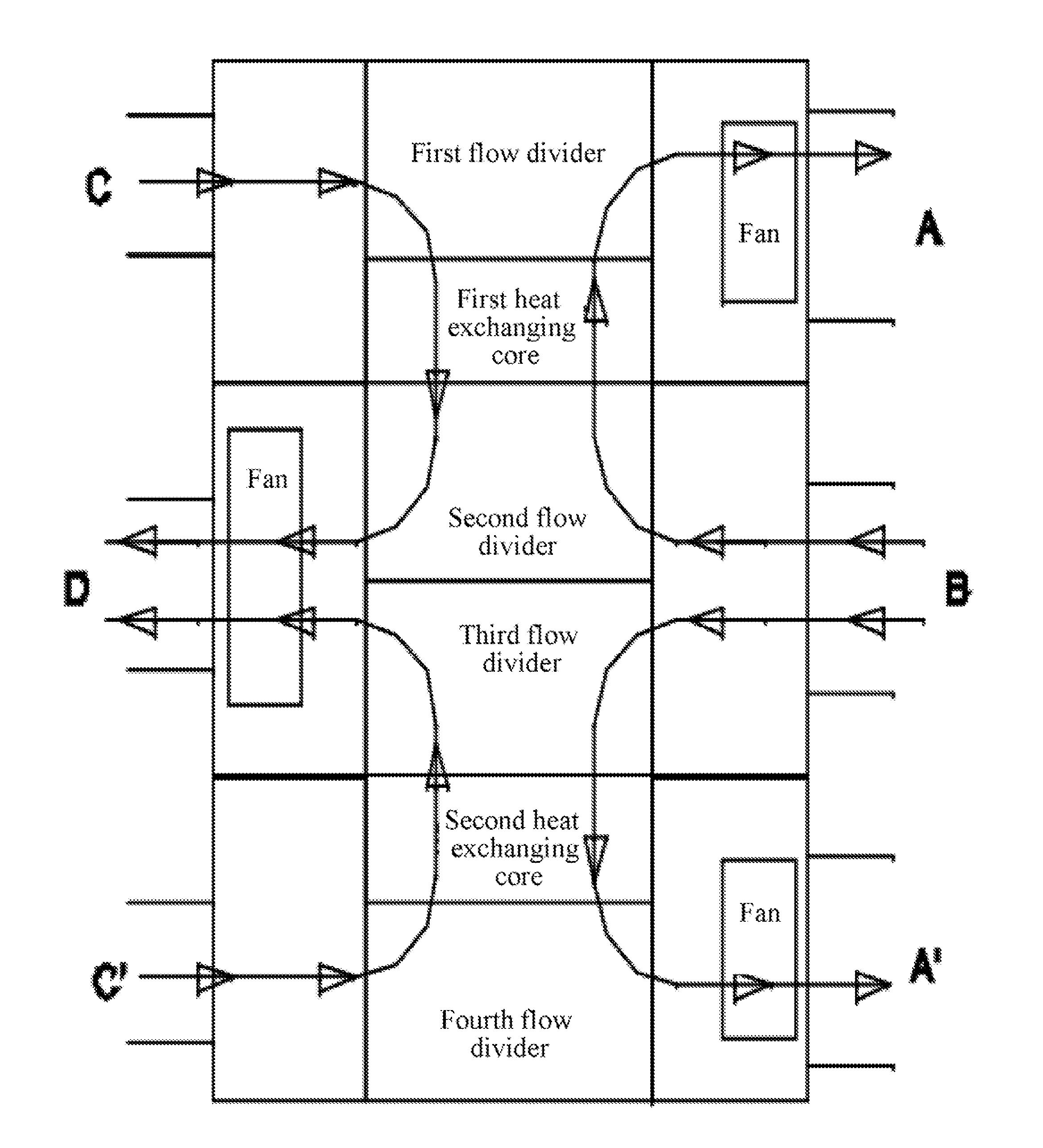
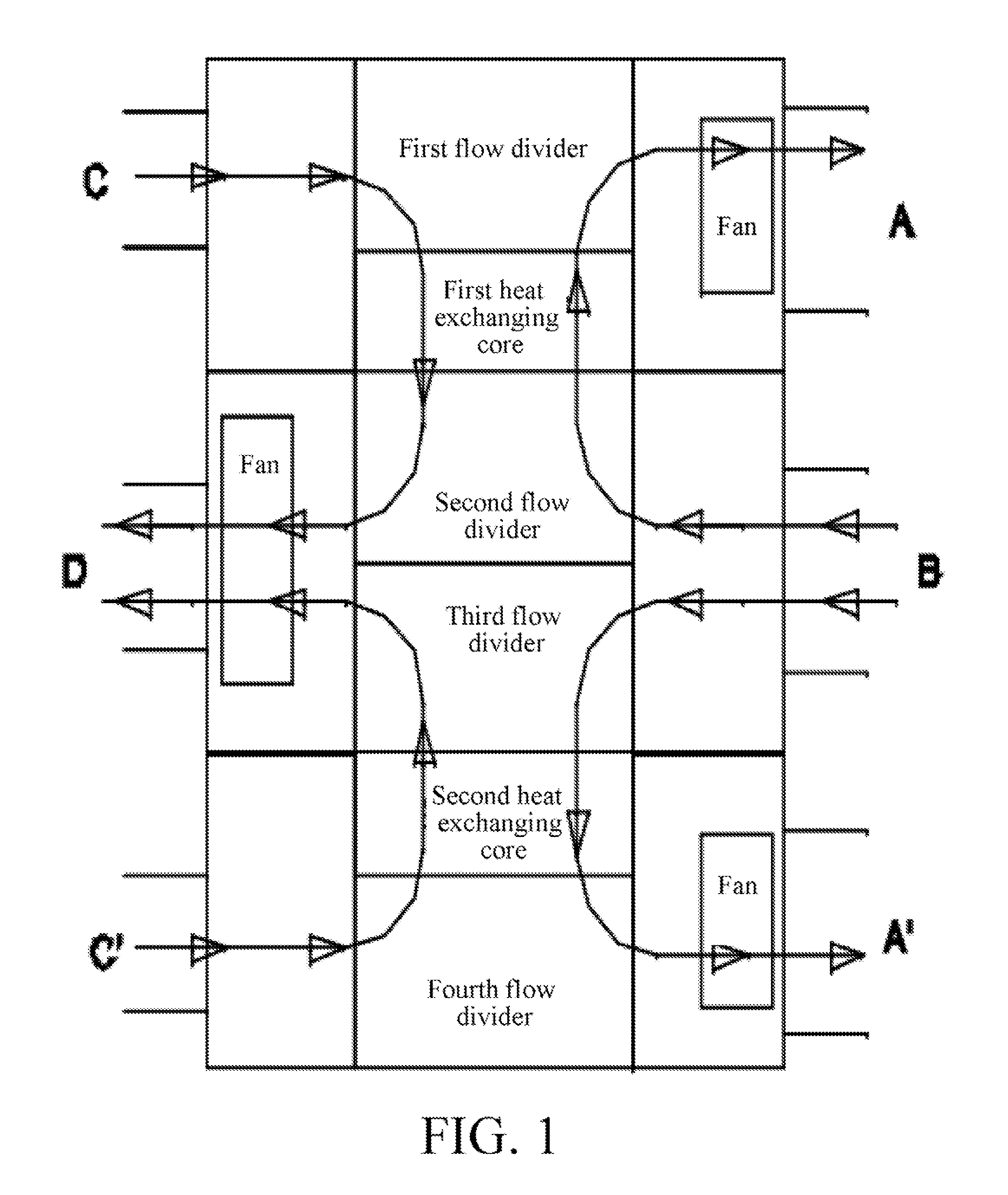
[0019]As shown in FIG. 1, a main body structure of an isolated counter-flow air heat exchanging device (an air heat exchanging device for short) provided in the present invention is formed with two heat exchanging cores, four flow dividers, three fans, and six air ports along a vertical direction. A first flow divider, a first heat exchanging core, a second flow divider, a third flow divider, a second heat exchanging core, and a fourth flow divider are disposed inside the main body structure from top to bottom. Three air ports are distributed respectively at two sides of the main body structure. Among the air ports, A, A′, D are air outlets, B, C, C′ are air inlets, and they form four wind channels independent from one another. The air port A, the first flow divider, the first heat exchanging core, the second flow divider and the air port B form a first wind channel, the air port C, the first flow divider, the first heat exchanging core, the second flow divider and the air port D fo...


PUM


Abstract

An isolated counter-flow air heat exchanging device with a vertical structure is provided, which includes two heat exchanging cores, four flow dividers, and six air ports. A first flow divider, a first heat exchanging core, a second flow divider, a third flow divider, a second heat exchanging core, and a fourth flow divider are disposed from top to bottom inside a main body structure, three air ports (A), (B), and (A′) are distributed at one side of the main body structure, and the other three air ports (C), (D), and (C′) are distributed at the other side of the main body structure parallel to this side. The first heat exchanging core and the second heat exchanging core are respectively formed with a plurality of heat sink fins, and each heat sink fin has a positive wind channel and a negative wind channel disposed at a distance. The air heat exchanging device occupies a small floor area. The two heat exchanging cores have large capacity, so the performance of heat exchange is large. Two sets of wind channels connected in parallel reduce the wind resistance, and therefore, power of the required fans is reduced, thereby greatly increasing the energy efficiency ratio.

Description

BACKGROUND OF THE INVENTION[0001]1. Field of Invention[0002]The present invention relates to an air heat exchanging device, in particular, to an isolated counter-flow air heat exchanging device, which has a plurality of isolated wind channels disposed in a heat exchanging core and realizes heat exchange through opposite air flows in the wind channels, and belongs to the field of air conditioning technology.[0003]2. Related Art[0004]Along with the development of the society, the number of used conventional air conditioning equipment increases significantly, and a large problem of energy sources is caused. In the 21st century emphasizing sustainable development issues such as environmental protection, energy-saving, safety, and reliability, how to reduce the energy consumption of the air conditioning equipment has become a common problem for manufacturers and users of the air conditioning equipment.[0005]In the operation of the air conditioning equipment, major energy consumption occu...

Claims


Application Information

Patent Timeline
Patent Type & Authority Applications(United States)
IPC IPC(8): F28F27/02
CPCF24F12/006Y02B30/563F28F27/02F28D9/0093F28F2250/104Y02B30/56
Inventor WANG, ZHEN
Owner TONLIER ENERGY TECHBEIJINGCO
Features
  • R&D
  • Intellectual Property
  • Life Sciences
  • Materials
  • Tech Scout
  • Unparalleled Data Quality
  • Higher Quality Content
  • 60% Fewer Hallucinations
Learn More