Rotation angle detection apparatus

a detection apparatus and rotational angle technology, applied in the direction of measuring devices, instruments, using electrical means, etc., can solve the problem that the detection element in the detection unit is subject to an error causing factor, and achieve the effect of high detection accuracy, stable absolute position processing, and easy design and manufacturing

Active Publication Date: 2011-12-29
OKUMA CORP
View PDF0 Cites 5 Cited by
  • Summary
  • Abstract
  • Description
  • Claims
  • Application Information

AI Technical Summary

Benefits of technology

[0026]According to a rotation angle detection apparatus according to one or more embodiments of the present invention, it is possible to cope with a request for various through hole sizes made by a machine side by relatively easy designing and manufacturing, while carrying out stable absolute position processing with high detection accuracy, and to produce an advantage of reduction in the development period and product cost. Further, as a single kind of detection unit can be used in various cases, stocks for maintenance can be significantly reduced.

Problems solved by technology

However, a problem is caused in that a detection element in the detection unit is subjected to an error causing factor, that is, an offset change caused by change in the curvature of a detection target.
An offset change of a detection element for detecting a magnetic flux density that will change due to the uneven part of a detection gear may become a direct cause of deterioration in detection accuracy, which is the most important criterion for a rotation angle detection apparatus, while an offset change of a detection element for detecting a magnetic flux density that will change due to the cut-offs of the absolute position encoding disk may provoke a possible error in binary determination, which may resultantly lead to an abnormal state, such as an error in absolute position processing.

Method used


Image

  • Rotation angle detection apparatus
  • Rotation angle detection apparatus
  • Rotation angle detection apparatus

Examples


Embodiment Construction

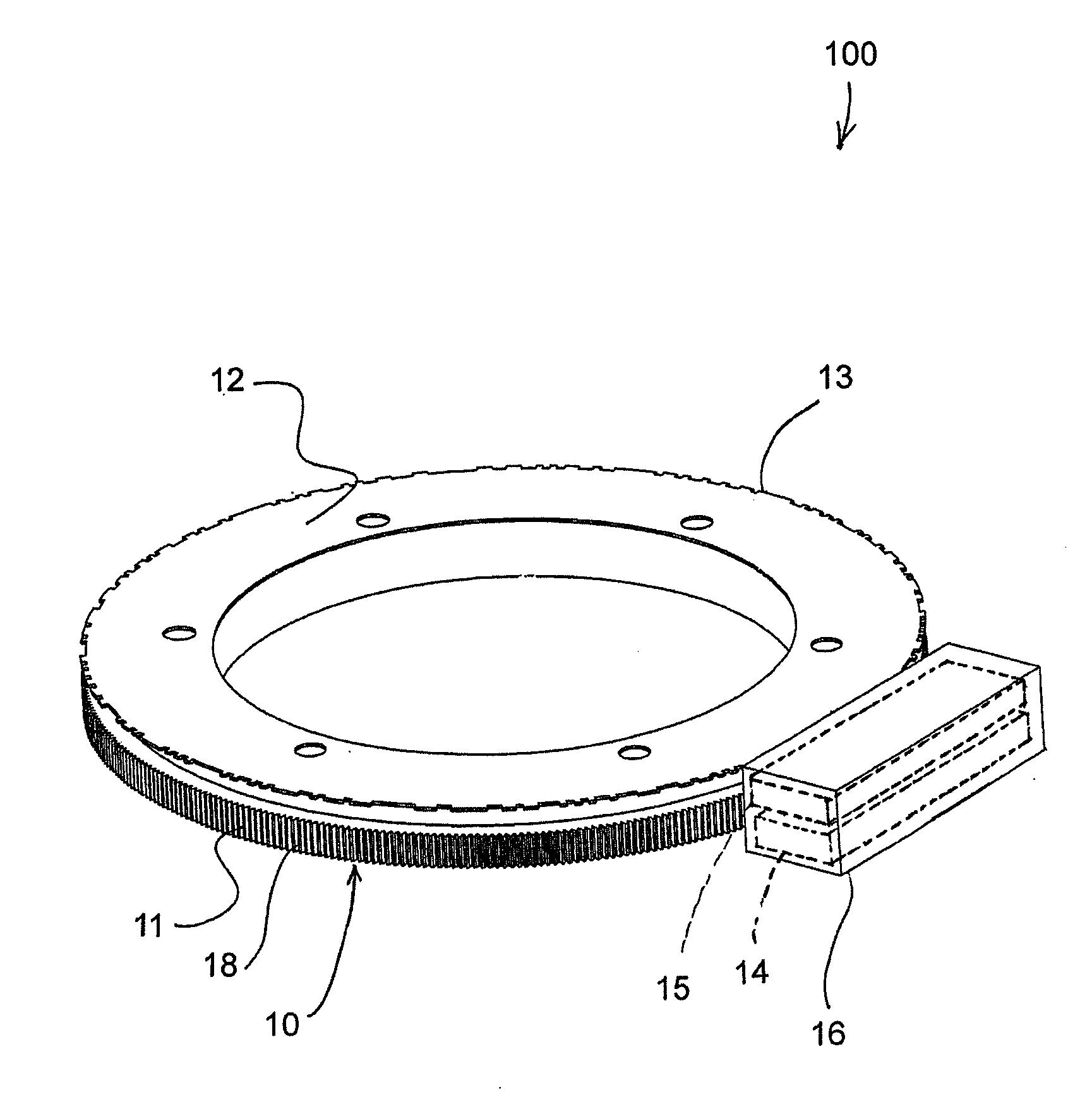
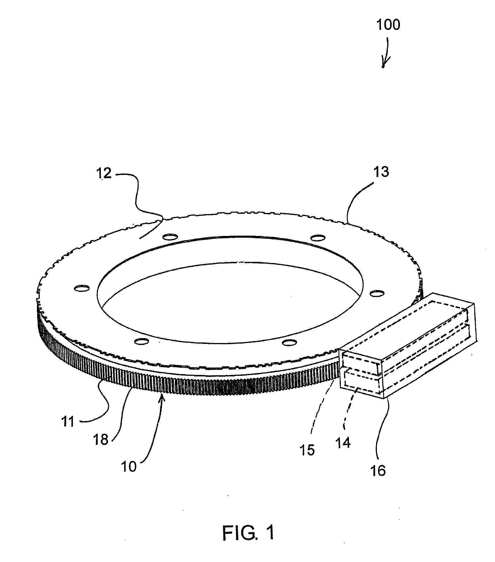
[0033]One or more embodiments of the present invention will be described referring to the accompanying drawings. As shown in FIG. 1, a rotation angle detection apparatus 100 in this embodiment comprises a detection target 10 including an incremental disk 11 and an absolute position encoding disk 12, and a detection unit 16. The incremental disk 11 has an n-time repetitive regular pattern and is coaxially and securely mounted on a rotation shaft or the like on the machine side that is a measurement target (not shown). The absolute position encoding disk 12 is mounted coaxial to the incremental disk 11, and has an irregular cyclic code comprising a binary random number sequence with an n-bit maximum length. The detection unit 16 is securely mounted on a non-rotating member, such as a flange, on the machine side (not shown).

[0034]The incremental disk 11 is a spur gear having n number of teeth, of which basic pitch length is about 1.256 mm. The absolute position encoding disk 12 has irr...


PUM


Abstract

In a rotation angle detection apparatus, a signal detected by a magnetoresistive element is digitalized before being subjected to subtraction of the optimum correction parameter therefrom in a subtractor, the optimum correction parameter being stored in advance in a memory. Note that during the initial transmission at the time of activation, the data size “n” of a detection target obtained by a CPU from a control device is transferred to the memory, so that the optimum correction parameter for the data size of the detection target is selected. With the above, the detection unit can relatively readily cope with a request for enlargement or the like of a through hole size made by a machine side, and detection accuracy is not deteriorated and an error in absolute position processing is reduced when the curvature of the detection target is changed.

Description

CROSS-REFERENCE TO RELATED APPLICATIONS[0001]This application claims priority to Japanese Patent Application No. 2010-142200, filed on Jun. 23, 2010, which is incorporated herein by reference in its entirety.BACKGROUND OF THE INVENTION[0002]1. Field of Invention[0003]One or more embodiments of the present invention relate to a rotation angle detection apparatus for use in fields of industrial machinery, machine tools, and so forth, and in particular, to a rotation angle detection apparatus having a detection unit that can cope with detection targets in a plurality of sizes.[0004]2. Background Art[0005]In response to an increasing demand for machining of extra-large parts in the fields of wind power generation, oil drilling, and the like, numbers of extra-large machine tools have been recently increased. Accordingly, the diameter of a rotation shaft has become larger, and so has that of a rotation angle detection apparatus mounted on the rotation shaft.[0006]FIG. 3 is a cross section...

Claims


Application Information

Patent Timeline
Patent Type & Authority Applications(United States)
IPC IPC(8): G01B7/30
CPCG01D5/2449G01B7/30
Inventor FUKUI, NORIYUKI
Owner OKUMA CORP
Why Eureka
Try Eureka