
Digital Intensive Baseband Chain Of A Receiver

a receiver and digital intensive technology, applied in the field of digital intensive baseband chain of receivers, can solve the problems of large chip size and power consumption, and achieve the effect of reducing power consumption

Active Publication Date: 2011-12-29
SILICON LAB INC
View PDF8 Cites 7 Cited by
  • Summary
  • Abstract
  • Description
  • Claims
  • Application Information

AI Technical Summary

Benefits of technology

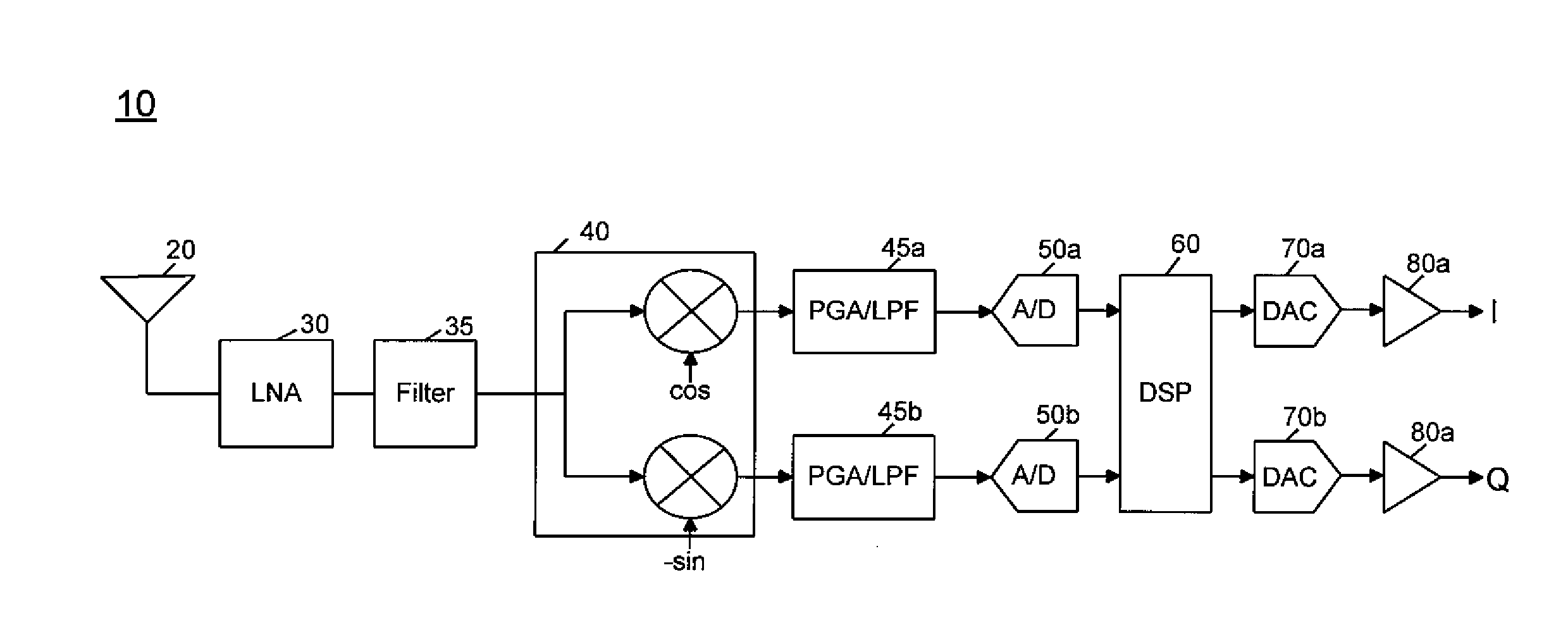
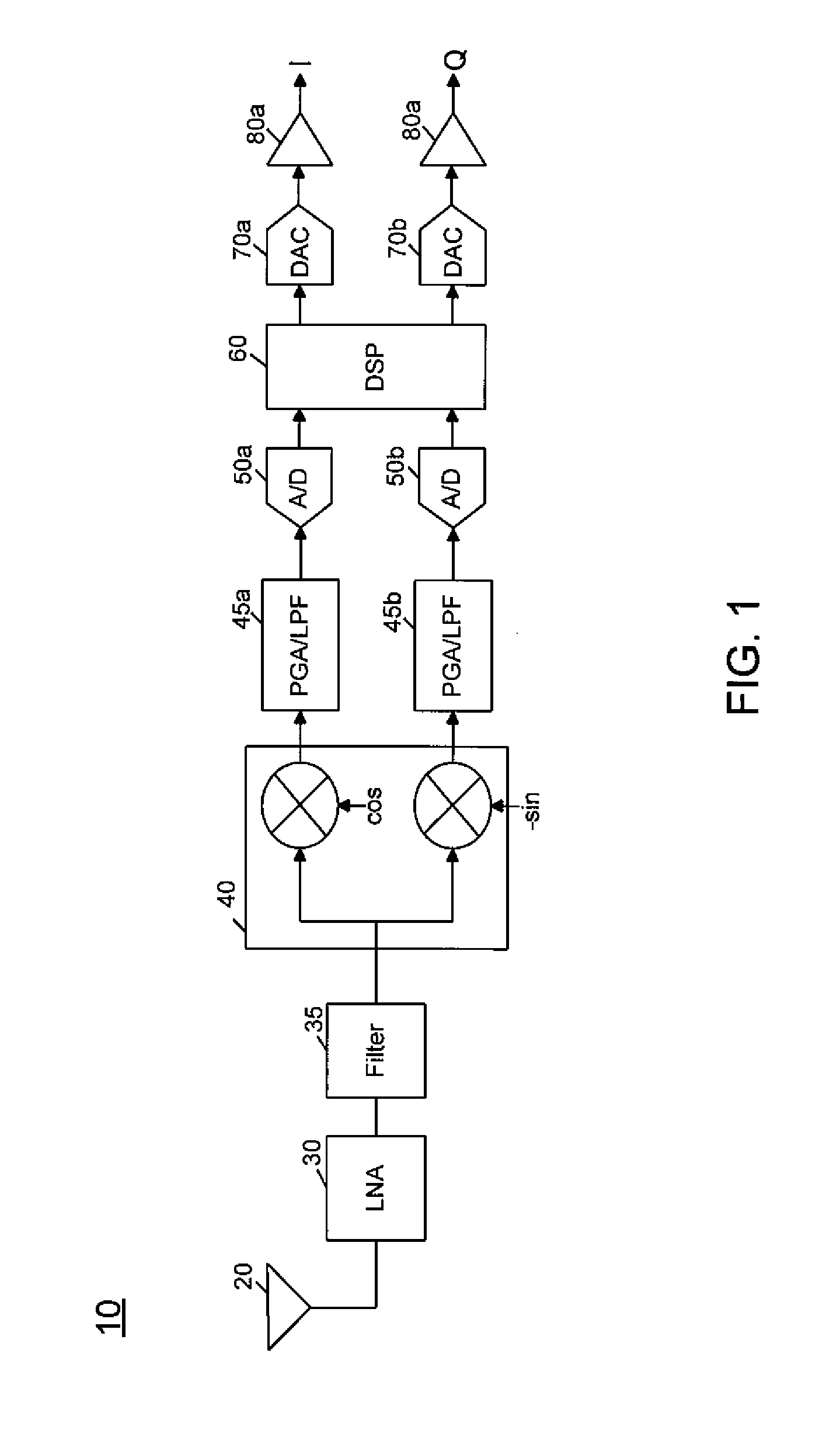
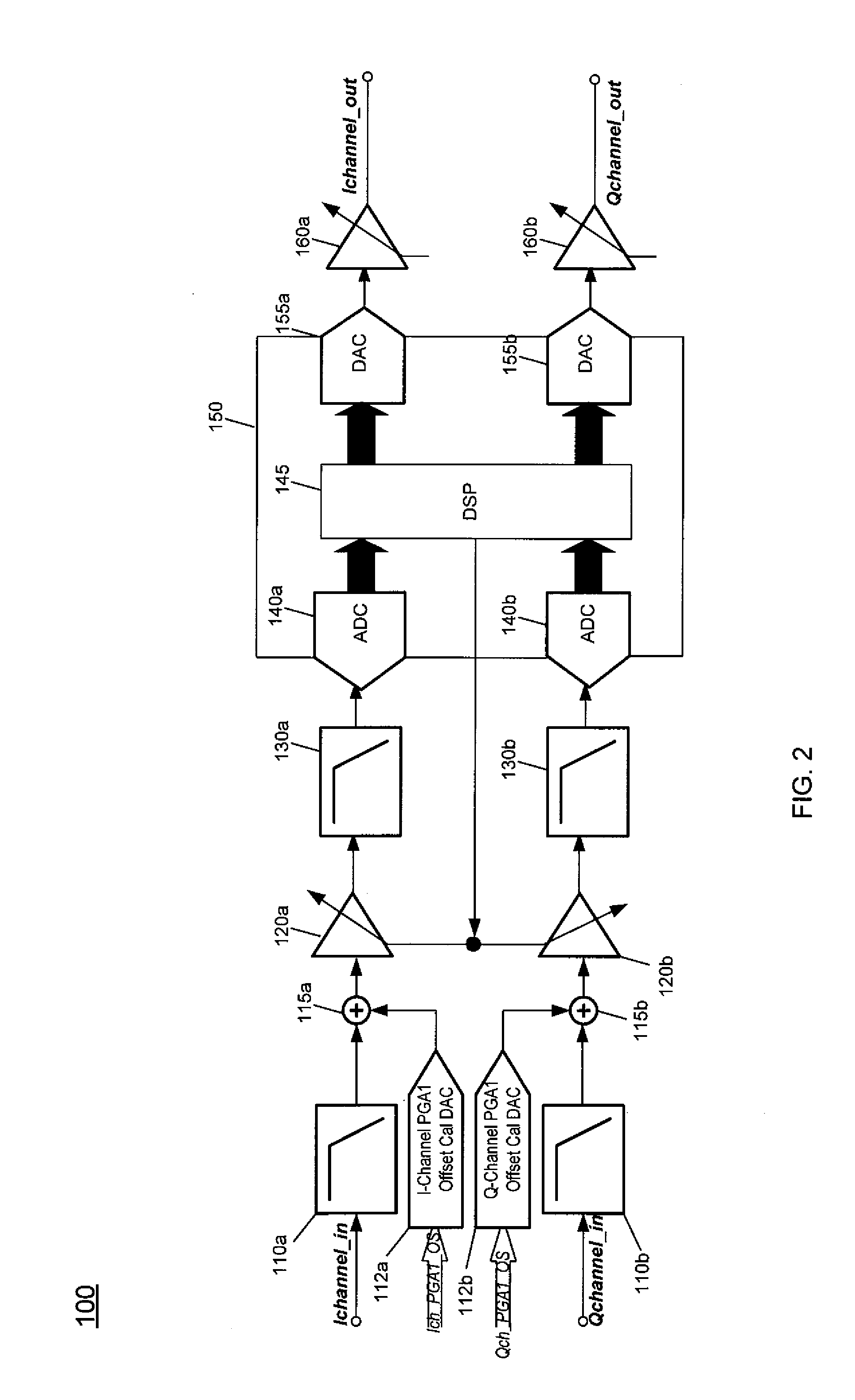
[0003]One aspect of the present invention is directed to an apparatus that includes various circuitry and is configured to perform channel filtering operations digitally, to reduce area and power consumption as compared to analog filtering. According to this aspect, the apparatus includes a mixer to downconvert incoming radio frequency (RF) signals to complex baseband signals, one or more programmable gain amplifiers (PGAs) coupled to the mixer to receive and amplify complex baseband signals, one or more passive filters coupled to the PGA(s) to filter the amplified complex baseband signals, digitization circuitry to convert the filtered baseband signals into digital complex signals, and a digital circuit, which may be implemented as a digital signal processor (DSP). The digital circuit may channel filter the digital complex signals, and provide them to conversion circuitry to convert the channel filtered digital complex signals to analog signals. In turn, output buffer circuitry can buffer the analog signals for output, where they may be provided to, e.g., an off-chip demodulator.
[0006]A still further aspect of the present invention is directed to a method for digitally filtering signals to reduce power consumption. The method includes downconverting an incoming RF signal to complex baseband signals in a complex mixer of a satellite tuner, filtering the complex baseband signals in one or more passive filters, converting the filtered complex baseband signals into digital complex signals, channel filtering the digital complex signals in a DSP, converting the channel filtered digital complex signals to analog signals, and outputting the analog signals from the satellite tuner.

Problems solved by technology

While such a design is relatively inexpensive, the size and power consumption of the chip can be relatively significant as certain circuitry, especially filtering circuitry, can require higher order complex filters.

Method used


Image

  • Digital Intensive Baseband Chain Of A Receiver
  • Digital Intensive Baseband Chain Of A Receiver
  • Digital Intensive Baseband Chain Of A Receiver

Examples


Embodiment Construction

[0011]In various embodiments, a television tuner can perform a significant amount of its tuner processing in the digital domain. In this way, reduced constraints can be realized for the analog circuitry of the tuner, as the channel filtering in various embodiments can be performed digitally. After digital processing to obtain a tuned signal suitable for demodulation, a conversion back to the analog domain may occur such that available downstream circuitry can demodulate the digitally processed signals. As described herein, a tuner may be in the context of a satellite television system, however, the scope of the present invention is not limited in this regard, and embodiments are equally applicable to other television systems as well as other wireless devices.

[0012]Referring now to FIG. 1, shown is a block diagram of a tuner in accordance with one embodiment of the present invention. In various implementations, tuner 10 may be a single chip integrated circuit such as a single die CMO...


PUM


Abstract

In one embodiment, the present invention is directed to an apparatus configured to perform channel filtering operations digitally, to reduce area and power consumption as compared to analog filtering. After passive filtering of downconverted analog baseband signals, the signals are provided to digitization circuitry to convert the filtered baseband signals into digital signals. Then a digital circuit, which may be implemented as a digital signal processor (DSP), may channel filter the digital signals and provide the filtered digital signals to conversion circuitry to convert the channel filtered digital signals back to analog signals.

Description

BACKGROUND[0001]Historically, televisions were formed of discrete analog components that received over-the-air channels and processed the received signals into video and audio signals for display and output from a television. As time has passed, television tuners and receivers are moving to more semiconductor-based technologies. This is especially so in light of the recent move to digital broadcasting and high-definition content.[0002]Signals can be received in a television in various ways, including over-the-air (or terrestrial), cable, satellite or in other manners. Different standards exist for different types of the signals. With regard to satellite television, a typical receive path includes a tuner to receive the signals from an antenna and to downconvert the signals to baseband. Such a tuner can be a single chip tuner that receives and processes the signals into analog baseband signals for output to downstream circuitry, namely another semiconductor chip, which may be a demod...

Claims


Application Information

Patent Timeline
Patent Type & Authority Applications(United States)
IPC IPC(8): H04N5/455H04L25/06H04L27/06
CPCH04L25/06H04L27/06H04N21/4382H04N21/42607H04N5/455
Inventor COBAN, ABDULKERIM L.RAFI, ASLAMALI A.
Owner SILICON LAB INC
Learn More