
Linear compressor

a compressor and linear technology, applied in the direction of machines/engines, positive displacement liquid engines, pumping machines, etc., can solve the problems of difficult to change the capacity of the capacitor cb>2/b>, difficulty in cost, space, design, etc., to prevent the phenomenon of stroke jump, vary or modulate the cooling capacity

Inactive Publication Date: 2011-12-29
LG ELECTRONICS INC
View PDF2 Cites 25 Cited by
  • Summary
  • Abstract
  • Description
  • Claims
  • Application Information

AI Technical Summary

Benefits of technology

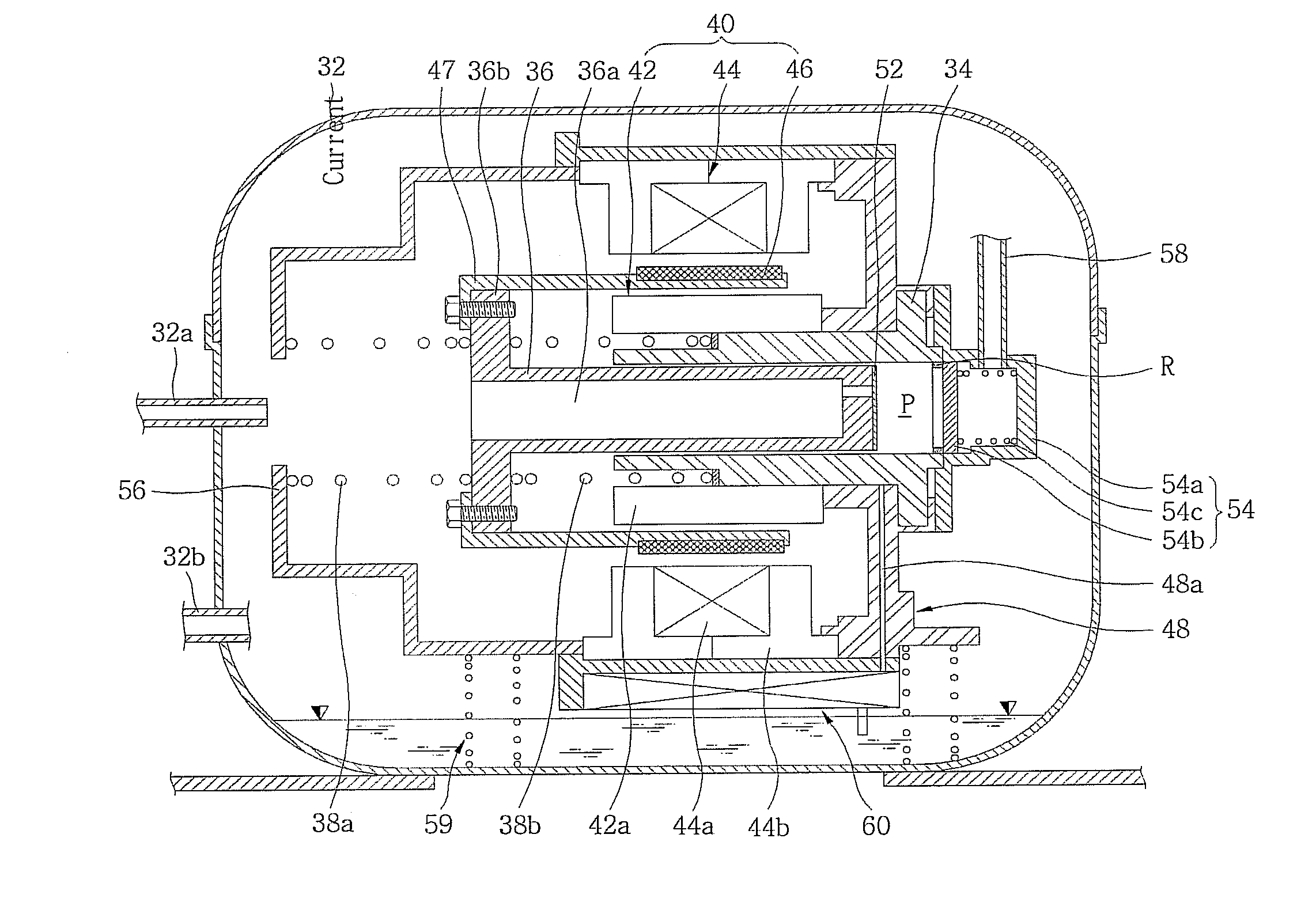
The present invention provides a linear compressor and a control method that can adjust the cooling capacity based on the load capacity, and can vary or modulate the cooling capacity as required, even when a cooling capacity greater than a load is necessary. The compressor includes a fixed member, a movable member, springs, a motor, a motor control unit, a current sensing unit, and a control unit. The control unit integrates the current sensed by the current sensing unit and controls the AC voltage applied to the motor to adjust the variable rate of cooling capacity. The control method includes applying a preset initial voltage to the motor, calculating the attenuation voltage, and applying the required voltage to the motor. The invention also prevents a stroke jump phenomenon and allows for the simple and rapid adjustment of the naturally variable rate of cooling capacity.

Problems solved by technology

Although the cooling capacity variability characteristics based on the load are determined by the capacity of the capacitor C2, conventionally, it is not easy to change the capacity of the capacitor C2.
Further, the provision and selective connection of a plurality of capacitors cause difficulties in terms of cost, space, and design.

Method used


Image

  • Linear compressor
  • Linear compressor
  • Linear compressor

Examples


Embodiment Construction

[0030]Hereinafter, exemplary embodiments of the present invention will be described in detail with reference to the attached drawings.

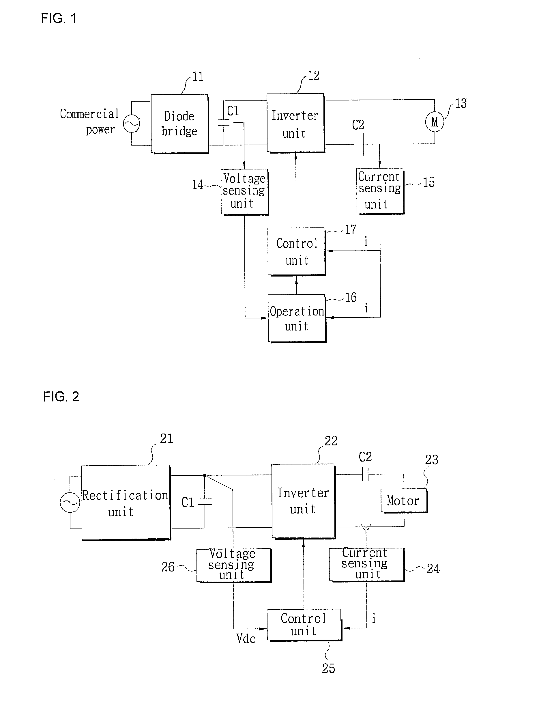
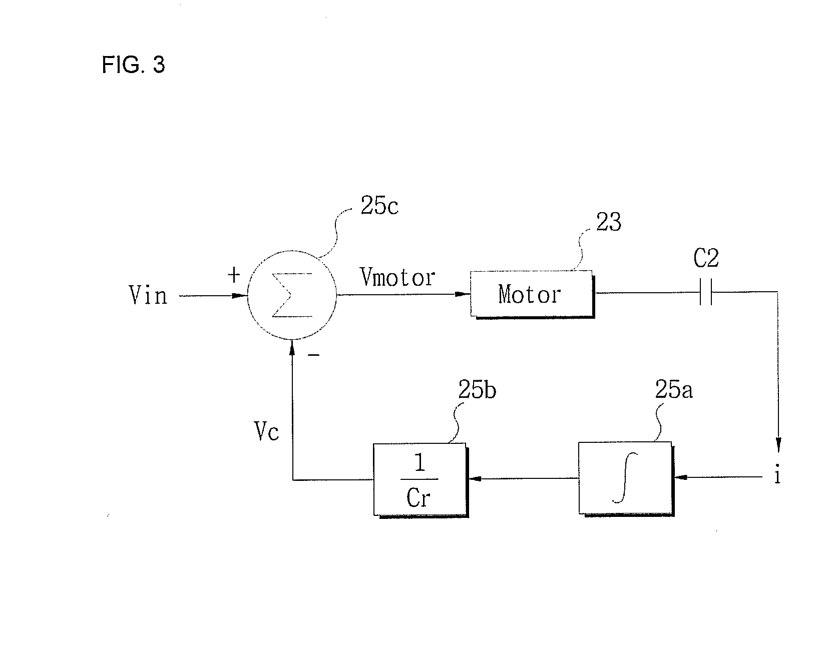
[0031]FIG. 2 is a block diagram of a control mechanism of a linear compressor according to the present invention and FIG. 3 is a circuit diagram of a control example of a control unit of FIG. 2.

[0032]As illustrated in FIG. 2, the control mechanism of the linear compressor includes a rectification unit 21 receiving, rectifying, smoothing, and outputting AC power which is commercial power, an inverter unit 22 receiving a DC voltage, converting the DC voltage to an AC voltage according to a control signal from a control unit 25, and supplying the AC voltage to a motor 23, a motor unit including a coil L and a capacitor C2 connected in series, a current sensing unit 24 sensing a current flowing between the motor unit and the inverter unit 22 or a current flowing through the coil L in the motor unit, the control unit 25 operating a motor application voltag...


PUM


Abstract

The present invention discloses a linear compressor which makes it possible to adjust a variable rate of a cooling capacity. The linear compressor includes a fixed member having a compression space therein, a movable member linearly reciprocated in the fixed member to compress a refrigerant sucked into the compression space, one or more springs provided to elastically support the movable member in the motion direction of the movable member, a motor unit including a motor connected to the movable member to linearly reciprocate the movable member in the axial direction and a capacitor connected in series to the motor, and a motor control unit controlling an AC voltage applied to the motor to adjust a variable rate of a cooling capacity by the reciprocation of the movable member.

Description

TECHNICAL FIELD[0001]The present invention relates to a linear compressor, and, more particularly, to a linear compressor which makes it possible to adjust a variable rate of a cooling capacity.BACKGROUND ART[0002]In general, a motor is provided in a compressor which is a mechanical apparatus for receiving power from a power generation apparatus, such as an electric motor, a turbine, etc. and compressing the air, refrigerant or other various operating gases to raise a pressure. The motor has been widely used in electric home appliances such as refrigerators, air conditioners, etc., and its application has been expanded to the whole industry.[0003]In particular, the compressors are roughly classified into a reciprocating compressor in which a compression space for sucking and discharging an operating gas is defined between a piston and a cylinder so that the piston can be linearly reciprocated in the cylinder to compress a refrigerant, a rotary compressor in which a compression space...

Claims


Application Information

Patent Timeline
Patent Type & Authority Applications(United States)
IPC IPC(8): F04B35/04
CPCF04B35/045F04B2203/0201F04B49/12F04B39/127F04B49/065H02K41/02F04B2203/0401F04B35/04F04B2203/0402F04B2207/046
Inventor HU, JIN SEOKPARK, SHIN HYUNKIM, YOUNG GEULKANG, KYO LYONG
Owner LG ELECTRONICS INC
Learn More