Apparatus and Method for Digitally Controlling Capacitance

a capacitance control and digital control technology, applied in the direction of pulse automatic control, pulse generator, pulse technique, etc., can solve the problems of circuits that cannot be used in typical applications such as mobile telephony, and change in output frequency, so as to prevent a loading effect

Active Publication Date: 2011-12-29
RICHWAVE TECH CORP
View PDF14 Cites 5 Cited by
  • Summary
  • Abstract
  • Description
  • Claims
  • Application Information

AI Technical Summary

Benefits of technology

[0006]An object of the embodiments described herein is to provide selective application of discrete amounts of capacitance to an electrical circuit, such as an oscillator circuit. In one embodiment there is provided an oscillator circuit, comprising an amplifier, a tank circuit comprising an inductor and a capacitor, and a discretely switchable capacitance module configured to control an amount of capacitance in the oscillator circuit. The discretely switchable capacitance module has a capacitor coupled between a first node and a second node, a switch, having a control node, coupled between the second node and a third node, and a DC feed circuit, having a first end coupled to the second node and a second end configured to receive a first control signal or a second control signal. The DC feed circuit could be a resistor or an inductor, and is used to apply the first or second control signal (which is a DC signal) to the second node and prevent output signal of the amplifier (which is an AC signal) to pass from first node to second end through the capacitor, and thus prevent a loading effect from the second end of the DC feed circuit.

Problems solved by technology

Thus, when the control voltage changes, the capacitance of the overall LC tank circuit changes, and, as a result, so does the resonant frequency of the LC circuit, thus causing a change in output frequency.
While such VCO implementations can be used in many applications, such circuits cannot typically be used in applications such as mobile telephony, in which very precise and discrete signal frequencies are needed to, among other purposes, avoid the potential for interference mentioned above.

Method used


Image

  • Apparatus and Method for Digitally Controlling Capacitance
  • Apparatus and Method for Digitally Controlling Capacitance
  • Apparatus and Method for Digitally Controlling Capacitance

Examples


Embodiment Construction

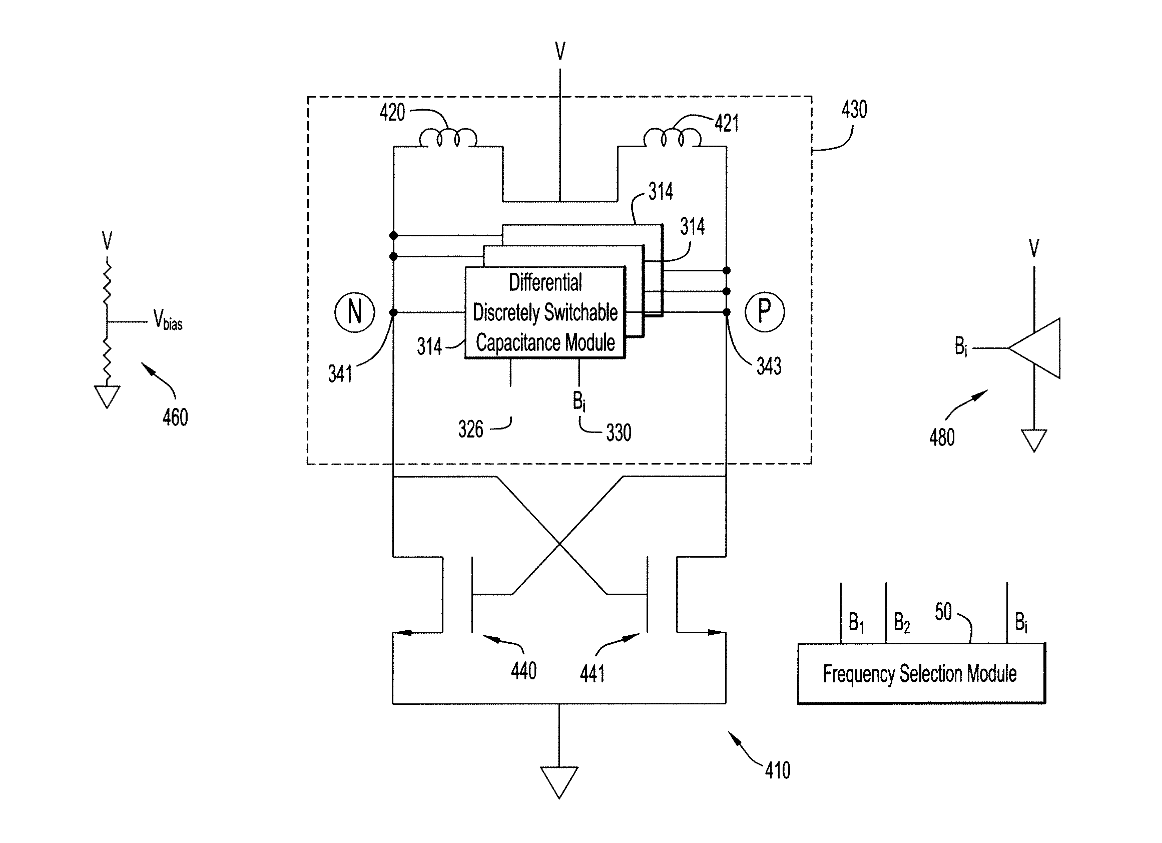
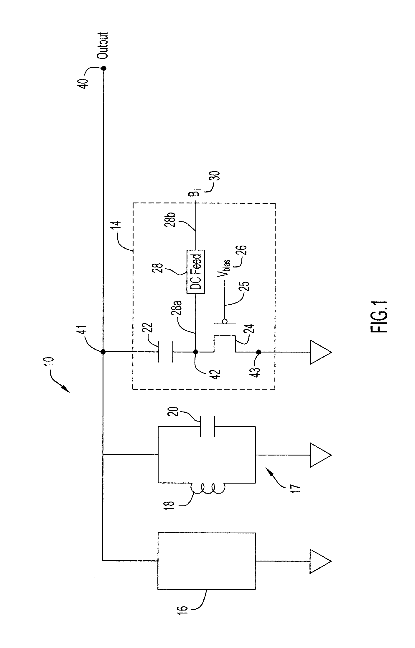
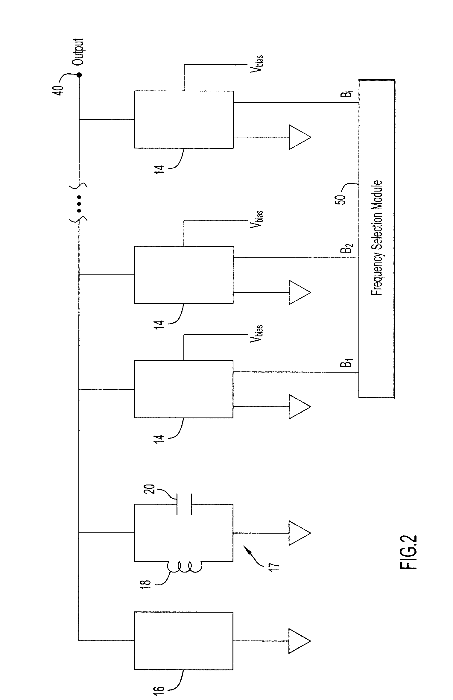
[0016]Referring to FIG. 1, there is shown a first embodiment of the present invention. An oscillator circuit 10, which may be part of an overall frequency synthesizer (which itself may be a component of a wireless communication device such as a mobile telephone) is shown that comprises an amplifier 16 that provides a source of oscillation. Amplifier 16 may be based on any number of designs known to those skilled in the art. An LC tank circuit 17 comprising an inductor 18 and a capacitor 20 provides an initial or default means for setting a frequency of oscillation. As will be explained below, additional capacitance can be selectively added via a discretely switchable capacitance module 14, a plurality of which may be provided as shown in FIG. 2.

[0017]More specifically, each discretely switchable capacitance module 14 includes a capacitor 22 electrically connected or coupled between a first node 41 and a second node 42. A switch 24, such as a PMOS FET, is coupled between the second n...


PUM


Abstract

An oscillator circuit having a source of an oscillating signal, a tank circuit including an inductor and a capacitor, and a discretely switchable capacitance module configured to control an amount of capacitance in the oscillator circuit. The discretely switchable capacitance module includes, in one embodiment, a capacitor coupled between a first node and a second node, a switch, having a control node, coupled between the second node and a third node; and a DC feed circuit, having a first end coupled to the second node and a second end configured to receive a first or second control signal. The control node of the switch is tied to a predetermined bias voltage. When the first control signal is applied, the capacitor is coupled between the first node and the third node via the switch such that the capacitor is coupled in parallel with the capacitor of the tank circuit, and when the second control signal is applied the capacitor is decoupled from the tank circuit.

Description

FIELD OF THE INVENTION[0001]The present invention relates to an oscillation circuit. More particularly, the present invention relates to a voltage controlled oscillator with digitally controlled application of discrete amounts capacitance.BACKGROUND OF THE INVENTION[0002]Many wireless devices such as mobile telephones require oscillation circuits to generate high frequency signals that may be mixed with incoming received signals and mixed with outgoing signals to be transmitted. In the case of mobile telephony, a given mobile telephone might have to operate across a broad range of frequencies or channels in order to avoid interfering with other mobile telephones.[0003]To provide this broad range of frequencies, a frequency synthesizer is often employed. A frequency synthesizer typically includes a controlled oscillator circuit, such as a voltage controlled oscillator (VCO) that receives a control voltage or signal and, in response thereto, alters or shifts the frequency of the VCO s...

Claims


Application Information

Patent Timeline
Patent Type & Authority Applications(United States)
IPC IPC(8): H04B1/40H03B21/00H03B5/12
CPCH03B5/1228H03B5/1265H03B5/1212H03B2201/0266H03J3/20H03J2200/10
Inventor TSE-PENG, CHEN
Owner RICHWAVE TECH CORP
Why Eureka
Try Eureka