
Photoacoustic imaging apparatus and photoacoustic imaging method

Inactive Publication Date: 2011-12-29
FUJIFILM CORP
View PDF0 Cites 23 Cited by
  • Summary
  • Abstract
  • Description
  • Claims
  • Application Information

AI Technical Summary

Benefits of technology

The present invention has been developed in view of the foregoing circumstances. It is an object of the present invention to provide a photoacoustic imaging apparatus and a photoacoustic imaging method that enables imaging while reducing the influence of jitters of pulsed laser beams even in cases that they occur.
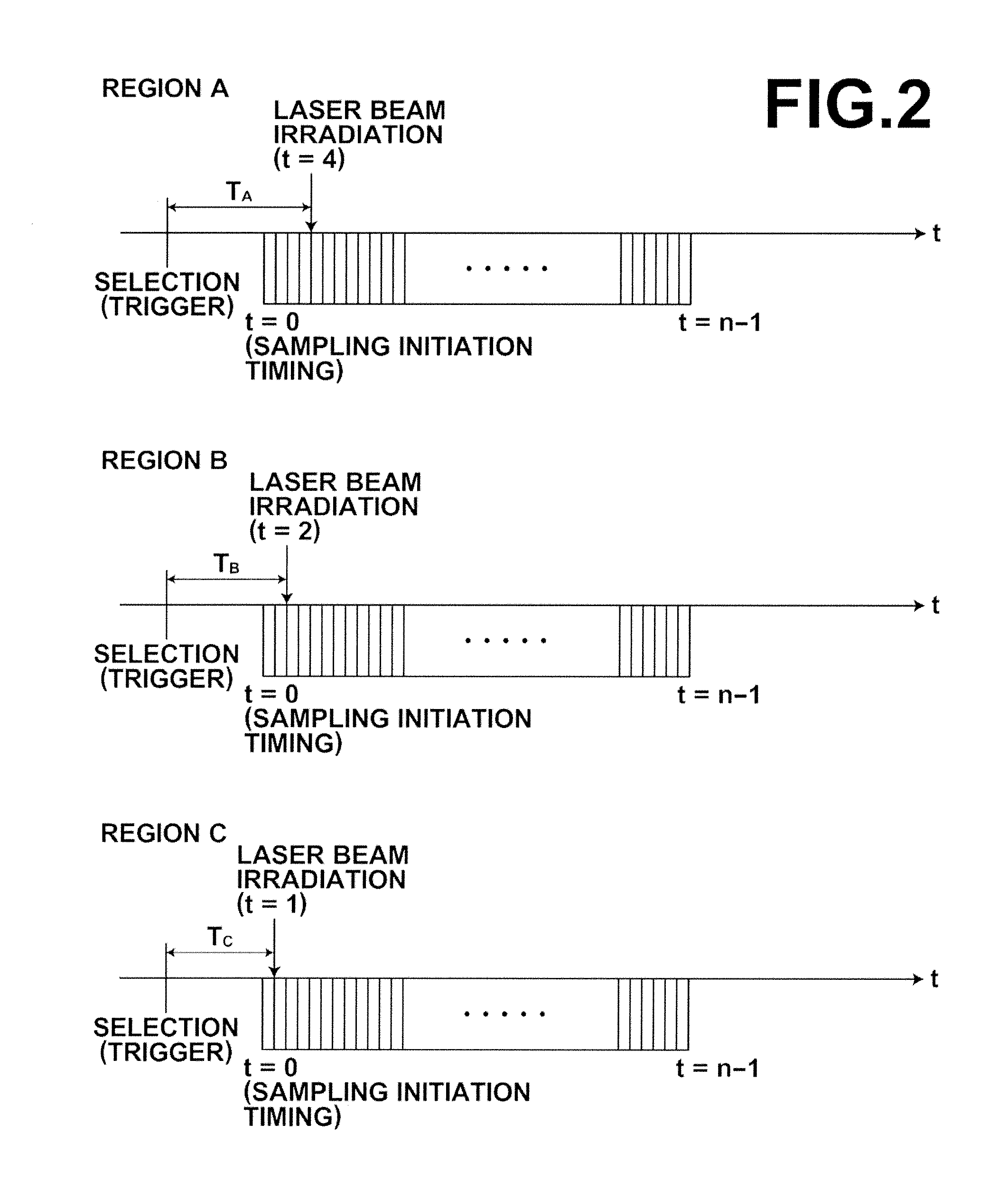
According to the photoacoustic imaging apparatus and the photoacoustic imaging method of the present invention, the plurality of partial regions, into which the range to be imaged of a subject is divided, are sequentially selected. Irradiation of light and sampling of acoustic signals generated by the irradiation of light are performed for each selected partial region. After selection of a partial region, the light irradiation timing is detected, and differences in the light irradiation timings are measured among the partial regions. The temporal axes of the data sampled from each partial region within the element data memory are corrected based on the measured differences. By adopting this configuration, errors due to fluctuations in light irradiation timings among the partial regions can be suppressed during image construction, even if the light irradiation timings differ among the partial regions. That is, the influence of jitters can be reduced in cases that they occur, and images having high image quality can be obtained.

Problems solved by technology

A problem to be solved to realize practical use of photoacoustic imaging is to increase the speed of imaging.
Therefore, the amount of time required to perform imaging becomes longer as the number of elements (number of channels) of the ultrasound probe increases.
Therefore, the intervals among light irradiating operations cannot be shortened beyond a certain degree.
Accordingly, there are limits to improvements in the imaging speed of the apparatus disclosed in Japanese Unexamined Patent Publication No. 2005-21380.
A / D converters that operate in parallel and at high speeds are expensive, and the cost of the system will increase because it will be necessary to provide a great number of such A / D converters.
That is, there is a possibility that jitters will occur in the laser pulses.
If jitters occur, errors will be generated between data obtained during the first light irradiating operation and data obtained during the second light irradiating operation, resulting in the image quality of images generated using the data deteriorating.

Method used


Image

  • Photoacoustic imaging apparatus and photoacoustic imaging method
  • Photoacoustic imaging apparatus and photoacoustic imaging method
  • Photoacoustic imaging apparatus and photoacoustic imaging method

Examples


Embodiment Construction

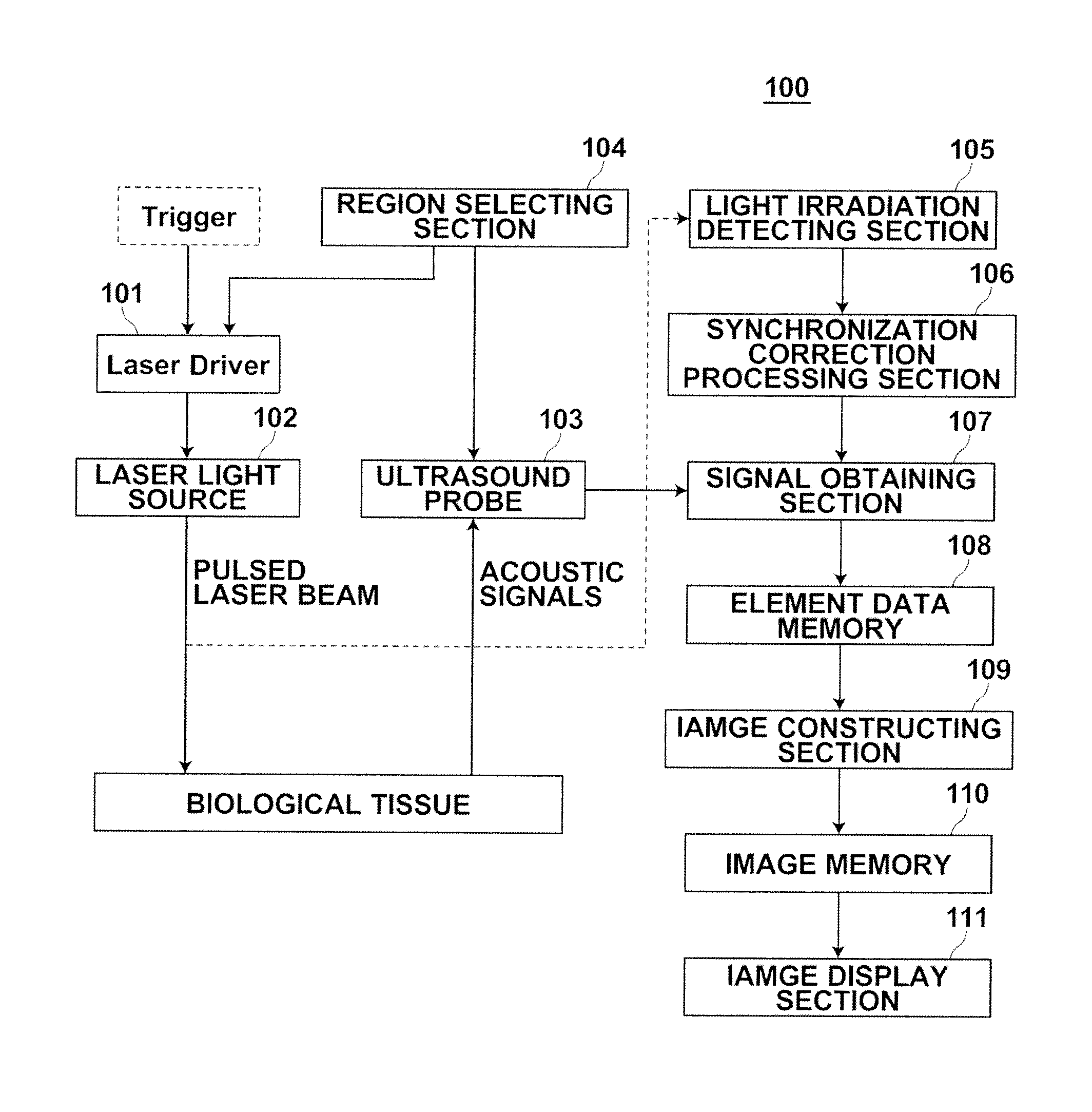
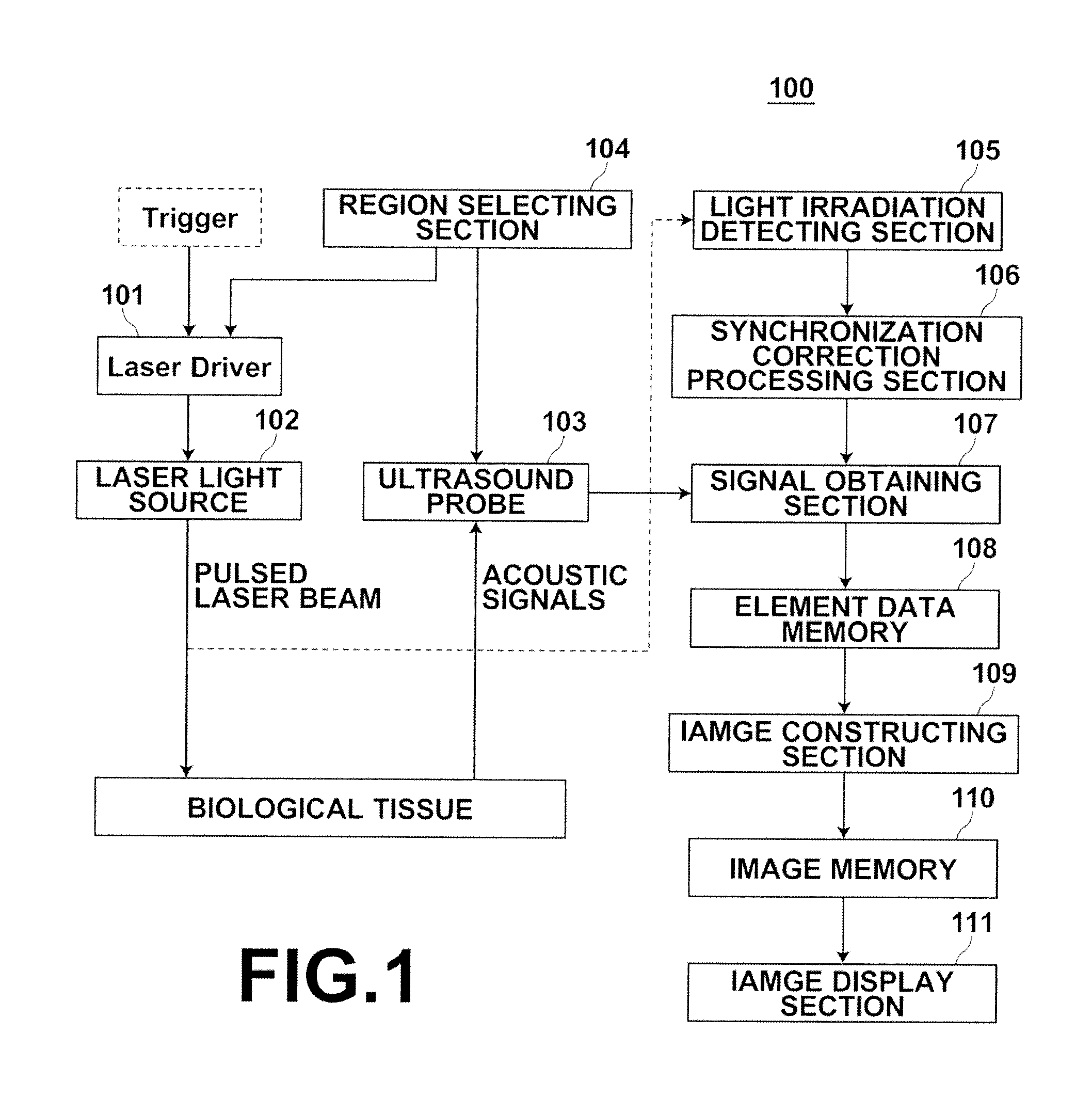
Hereinafter, embodiments of the present invention will be described in detail with reference to the attached drawings. FIG. 1 is a diagram that illustrates a photoacoustic imaging apparatus according to an embodiment of the present invention. The photoacoustic imaging apparatus 100 is equipped with: a laser driver 101; a laser light source 102; an ultrasound probe 103; a region selecting section 104; a light irradiation detecting section 105; a synchronization correction processing section 106; a signal obtaining section 107; an element data memory 108; an image constructing section 109; an image memory 110; and an image display section 111.

The laser driver 101 drives the laser light source 102. The laser light source 102 outputs a pulsed laser beam to biological tissue, which is a target of examination, when generating photoacoustic images. A Q switch solid state laser, for example, may be employed as the laser light source 102. Trigger signals are input to the laser driver 101, an...


PUM


Abstract

A region selecting means sequentially selects a plurality of partial regions, into which a range to be imaged of a subject is divided. A light irradiation detecting section detects light which is irradiated onto the subject from a laser light source. A signal obtaining section samples acoustic signals detected by probe elements corresponding to the selected partial region, and stores the acoustic signals in an element data memory. An image constructing section constructs a tomographic image of the subject based on the data read out from the element data memory. A synchronization correction processing section obtains the differences in the timings at which the light irradiation detecting section has detected irradiation of light, and corrects the temporal axes of the sampled data in the element data memory based on the obtained timing differences.

Description

BACKGROUND OF THE INVENTION1. Field of the InventionThe present invention is related to a photoacoustic imaging apparatus and a photoacoustic imaging method. More specifically, the present invention is related to a photoacoustic imaging apparatus and a photoacoustic imaging method that performs imaging based on acoustic signals generated by light which is irradiated onto a subject.2. Description of the Related ArtPhotoacoustic imaging, which images the interiors of living organisms utilizing the photoacoustic effect, is known. Generally, in photoacoustic imaging, pulsed laser beams such as laser pulses are irradiated into the living organisms. Biological tissue that absorbs the energy of the pulsed laser beams generate acoustic waves (acoustic signals) by volume expansion thereof due to heat. The acoustic waves are detected by an ultrasound probe or the like, and the detected signals are utilized to enable visualization of the living organisms based on acoustic waves.Japanese Unexam...

Claims


Application Information

Patent Timeline
IPC IPC(8): A61B6/00
CPCA61B5/0095A61B8/469A61B8/4444
Inventor TSUJITA, KAZUHIROISHIHARA, MIYA
Owner FUJIFILM CORP
Learn More