Gas trap for drilling mud having quick-release separable lower section

Active Publication Date: 2012-01-05
RIGSAT COMM
View PDF4 Cites 20 Cited by
  • Summary
  • Abstract
  • Description
  • Claims
  • Application Information

AI Technical Summary

Benefits of technology

[0021]In a further (optional) embodiment, the shaft itself has quick-release coupling means thereon to permit quick release of said shaft and / or stirring means thereon, to thereby facilitate rapid replacement of said shaft and / or stirring means. In a particular embodiment, the gas trap apparatus has coupling means situated on the beater bars, which permit quick release of said beater bars from said shaft, to thereby facilitate rapid replacement of said beater bars. In another embodiment, the shaft has quick release coupling means which engage the motor and shaft, to permit quick release of a used shaft and beater bars, and quick coupling of a new shaft and beater bars to the motor. Such quick-release coupling means can be of any type, but in a preferred embodiment is a “pin and groove” arrangement, whereby a protruding pin or other protuberance releasably engages a corresponding groove in the mating component, to provide such quick-release coupling of the two components.

Problems solved by technology

Problematically, due the drilling mud containing significant abrasives, not the least of which is drill chips entrained therein from drilling operations, as well as having (and being designed to entrain therewithin) suspended solid particles, such drilling mud and abrasive particles therein causes serious and substantial wear to rotating outwardly-radially extending “beater bars” on the agitator shaft, frequently resulting (depending on the speed of rotation of the shaft and the amount of abrasives contained in the drilling mud) in breakage and / or substantial material loss of the beater bars, all of which result in ineffective or reduced effective operation of the agitation of the drilling mud and thus the gas trap, requiring servicing of or replacement of the shaft and / or one or more beater bars of the gas trap.
Thus a significant disadvantage of each of the prior art gas traps and their designs is that the container (or plates) which surround the shaft make replacement or access to the shaft difficult or impossible.
Although such design, being of a two part construction, allowed access to the shaft upon removal of the threaded bolts, such was time consuming and often resulted in loss of bolts within the mud tanks upon which the gas traps were mounted.

Method used


Image

  • Gas trap for drilling mud having quick-release separable lower section
  • Gas trap for drilling mud having quick-release separable lower section
  • Gas trap for drilling mud having quick-release separable lower section

Examples


Embodiment Construction

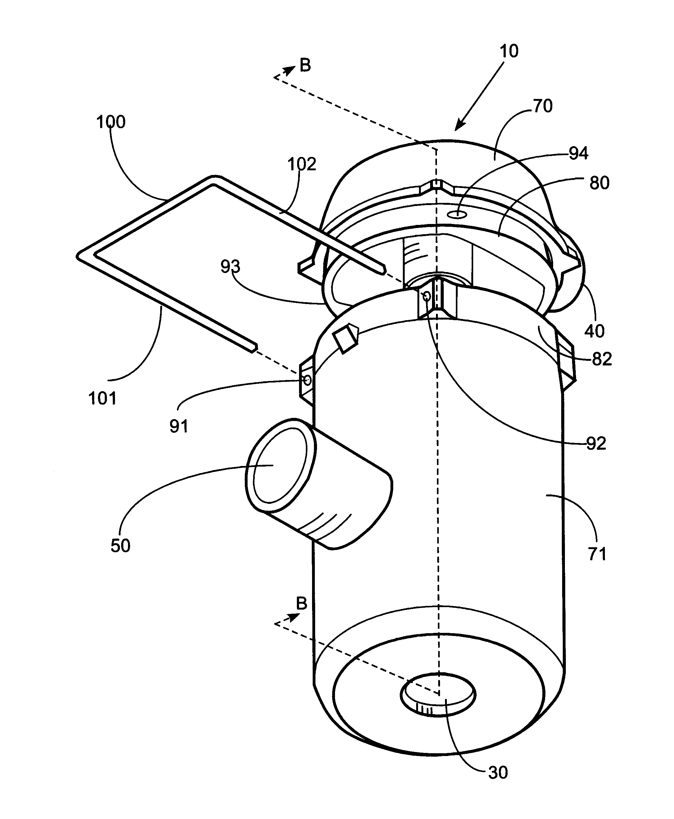
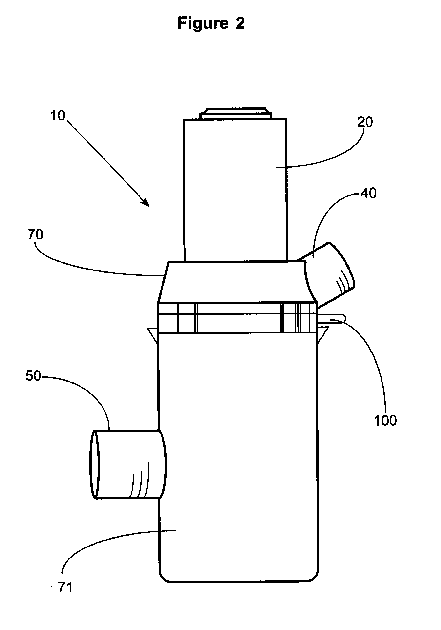
[0039]FIG. 1 shows a gas trap 10 of the prior art for stimulating release of any gas “G” which is entrained in drilling mud 11.

[0040]FIG. 1 shows the manner of operation of a prior art gas trap 10, when such gas trap 10 is attached via attachment means 14 (which may be any type of attachment, such as by bolting, or simply hanging) to the side of a mud tank 12.

[0041]In operation, motor means 20 turns rotating shaft 22, which in turn rotates “beater bars”24 which agitate drilling mud 11 in gas trap 10. Drilling mud 11 flows into mud entry aperture 30 in the bottom of gas trap 10 (see arrows directed into aperture 30), and the rotation of beater bars 24 releases gas “G”. Entrained gas “G” flows upwardly in gas trap 10, and is drawn by means of vacuum pressure or the like through gas collection port 40 on the gas trap 10 to a gas sampler device (not shown). Drilling mud 11 (with entrained gas “G” removed therefrom) then exits gas trap 10 via mud exit aperture 50, whereupon such drilling...


PUM


Abstract

A gas trap apparatus for liberating gas from drilling mud and collecting such gas for analysis. A motor is connected to a rotatable vertical shaft having beater bars thereon, which when the shaft is immersed in drilling mud and rotate, stirs such mud to liberate gas entrained therein. The gas trap is characterized in having a top member and a bottom member which surrounds the vertical shaft and which is releasibly secured to the top member thereof by a quick release mechanism which facilitates rapid detachment of the bottom member from the top member to permit quick access said vertical shaft and beater bars thereon for replacement or servicing. The vertical shaft may further likewise be provided with a quick-release means to allow quick release of the shaft from the motor for easy replacement and servicing of same.

Description

FIELD OF THE INVENTION[0001]The invention relates to a gas trap apparatus for mud logging when drilling for hydrocarbons.BACKGROUND OF THE INVENTION AND DESCRIPTION OF THE PRIOR ART[0002]“Drilling mud” is a generic term for a fluid containing dispersed solids which is used in the drilling of wells. Drilling mud, comprising various chemical compounds, is pumped down the drill string during the drilling of a well to assist, among other things, in cooling the drill bit, minimizing corrosion of drill pipe, pressurizing the well against hydrostatic head when the drill string enters a pressurized formation, and further to carry drill chips away from the drill bit, which then become suspended in such drilling mud. The drilling mud flows back to surface, typically in the annulus between the drill string and the well casing.[0003]When a hydrocarbon-containing strata is encountered during drilling of a well, a certain amount of the gas containing hydrocarbons from the strata will be entrained...

Claims


Application Information

Patent Timeline
IPC IPC(8): E21B47/00
CPCB01D19/0052E21B21/067G01N2001/1025G01N1/22E21B49/005E21B21/01
Inventor PHILLIPS, TERENCE D.
Owner RIGSAT COMM
Why Eureka
Try Eureka