Physical quantity sensor

a sensor and physical technology, applied in the field of physical quantity sensors, can solve problems such as unstable circuits, and achieve the effect of detecting stably strain and tension acting on objects

Inactive Publication Date: 2012-01-05
PANASONIC CORP
View PDF28 Cites 20 Cited by
  • Summary
  • Abstract
  • Description
  • Claims
  • Application Information

AI Technical Summary

Benefits of technology

[0008]This physical quantity sensor can stab...

Problems solved by technology

The change will make the circuit unstab...

Method used


Image

  • Physical quantity sensor
  • Physical quantity sensor
  • Physical quantity sensor

Examples


Embodiment Construction

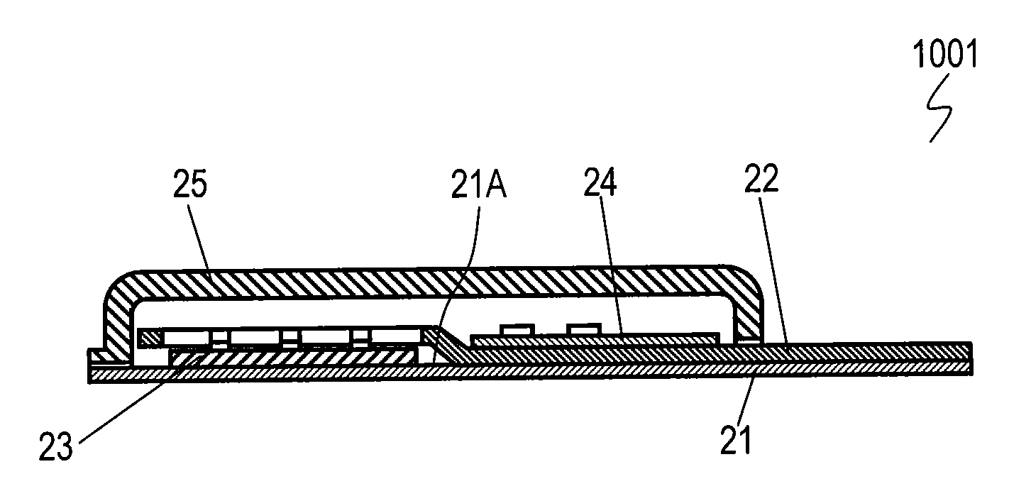
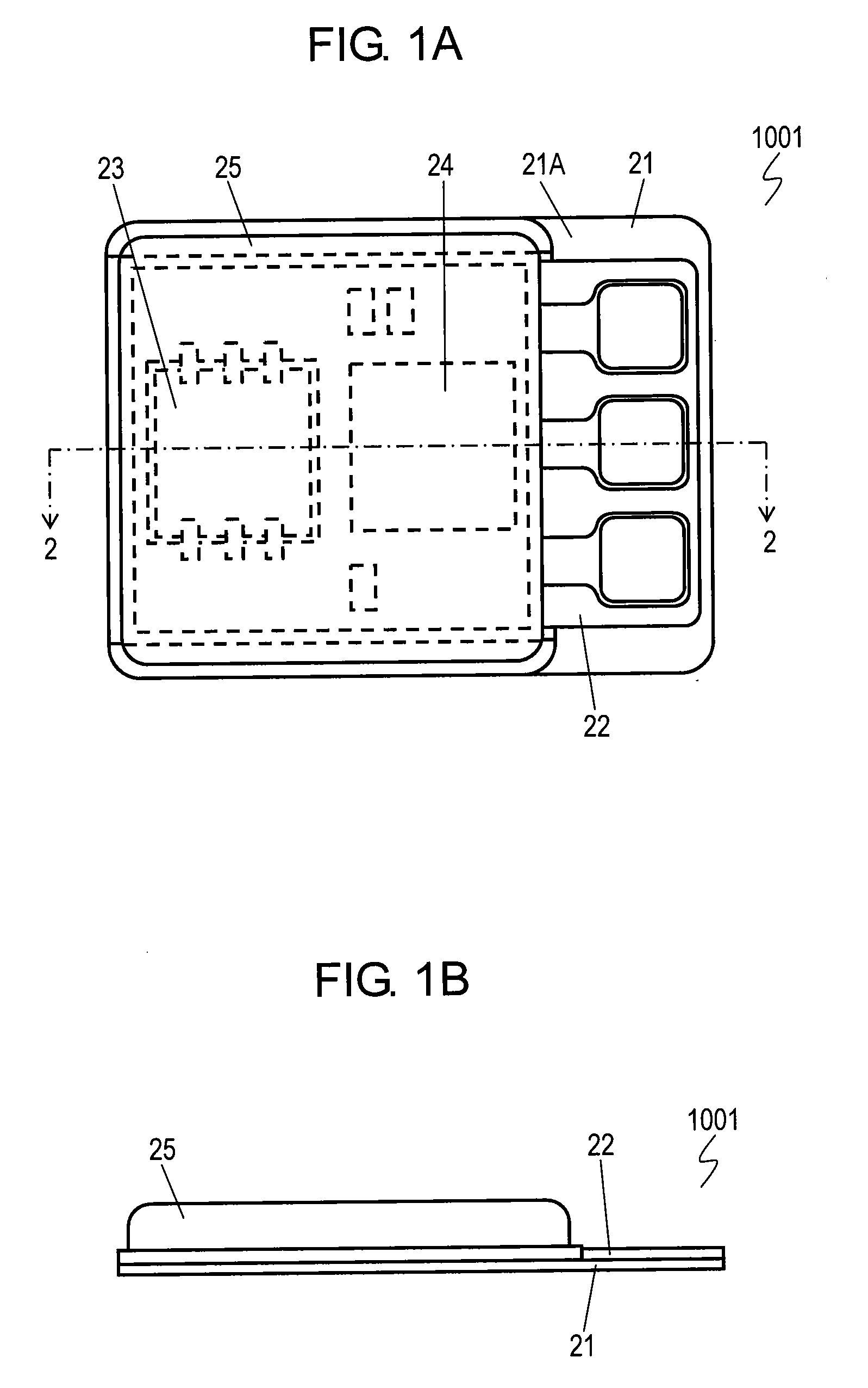
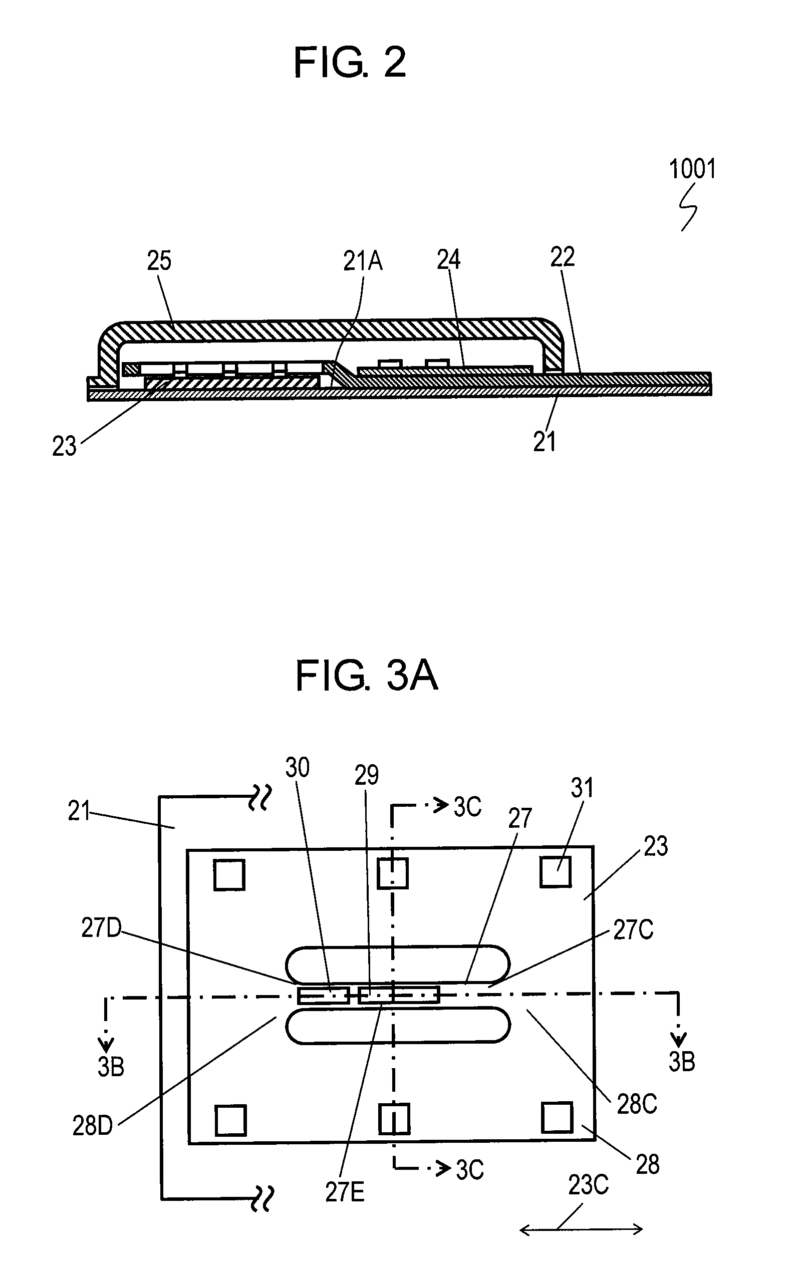
[0019]FIGS. 1A and 1B are a top view and a side view of physical quantity sensor 1001 according to an exemplary embodiment of the present invention, respectively. FIG. 2 is a cross-sectional view of physical quantity sensor 1001 taken along line 2-2 shown in FIG. 1A. Deformable body 21 is made of metal, such as stainless steel, and generates strain by a stress applied thereto. Flexible substrate 22 made of flexible material, such as polyimide film, is provided on upper surface 21A of deformable body 21. Vibrator 23 and processor 24 are mounted onto flexible substrate 22. Vibrator 23 vibrates with a vibration frequency that changes according to the amount of the strain occurring in deformable body 21. Processor 24 includes electronic components, such as an integrated circuit (IC) and a resistor, and processes a signal output from vibrator 23. Package 25 made of ceramic or metal is mounted to deformable body 21 so as to entirely accommodate and protect vibrator 23 and processor 24.

[00...


PUM


Abstract

A physical quantity sensor includes a deformable body in which strain occurs in response to a stress applied thereto, a vibrator vibrating with a frequency according to the strain or with an amplitude according to the strain, and a processor processing a signal output from the vibrator. The vibrator is mounted to the deformable body such that the strain transmits to the vibrator. The processor is bonded to the deformable body such that the strain does not substantially transmit to the processor. This physical quantity sensor can stably detects strain and tension acting on an object.

Description

[0001]This application is a U.S. National Phase Application of PCT International Application PCT / JP2010 / 001588.TECHNICAL FIELD[0002]The present invention relates to a physical quantity sensor for detecting strain and tension acting on an object.BACKGROUND ART[0003]Physical quantity sensors of high performance and small size for detecting strain and tension acting on an object, have been recently developed by applying a micromachine technologies. FIG. 6 is a cross-sectional view of conventional physical quantity sensor 501 described in Patent Literature 1. Insulating layer 222 made of silicon oxide or silicon nitride is formed on a surface of semiconductor substrate 1 made of material including silicon. A vibration-element portion which has lower electrode 3 and upper electrode 5 made of polysilicon or metal are formed on a surface of insulating layer 222. Upper electrode 5 is an elastic body having a ribbon shape, and has both ends in longitudinal direction fixed to the surface of i...

Claims


Application Information

Patent Timeline
IPC IPC(8): G01N29/12
CPCG01L1/183
Inventor MATSUURA, AKIRAOHKOSHI, HIDEONAKANISHI, TSUTOMUKAWAI, TAKASHI
Owner PANASONIC CORP
Why Eureka
Try Eureka