Thermal switch

a technology of switch and resistor, applied in the field of thermal switches, can solve the problems of large current loss, large power loss in the resistor portion, and significant ill effects of reducing the lifetime of the power supply switch or the rectifying diode, and achieve the effects of fast thermal response, and reducing power loss and producing hea

Inactive Publication Date: 2012-01-05
UCHIYA THERMOSTAT
View PDF20 Cites 12 Cited by
  • Summary
  • Abstract
  • Description
  • Claims
  • Application Information

AI Technical Summary

Benefits of technology

[0027]According to the present invention, both ends of a current limit resistor after an inrush current is limited are short-circuited to reduce a power loss and produced heat, which are caused by the current limit resistor, and moreover, heat is produced by applying a power supply current branched to the current limit resistor and a self-switch circuit to an included resistance part with short-circuiting of both the ends of the current limit resistor. As a result, the temperature of a bimetal in the self-switch circuit can be retained to a restoration temperature or higher with the heat produced by the self-switch circuit even though the temperature of the current limit resistor goes down after the inrush current is limited.
[0028]Additionally, pulsation of a direct current power supply is removed by resolving repetitions of useless operations and restoration, and at the same time, a power supply switch is quickly restored owing to a fast thermal response when being turned off. Accordingly, the current limit resistor can be made to function efficiently even though the power supply switch opens / closes at a short interval.

Problems solved by technology

If an inrush current is high as described above, significant ill effects of reducing the lifetime of a power supply switch or a rectifying diode are exerted.
If a resistor used as a current limit resistor is a fixed resistor, a current loss becomes large.
However, if a resistor is used in this way, a power loss in a resistor portion becomes large.
Minimization of an energy loss in an electric appliance is a social challenge also from the viewpoint of recent environmental problems.
However, also the above described power loss caused by a current limit resistor in a power supply circuit is an important issue, and reducing the power loss caused by the current limit resistor has been studied as measures against such an issue.
However, this method aims at preventing the current limit resistor from being burnt, and power is consumed to drive the relay.
Therefore, this method is useless for an objective of reducing the power loss caused by the current limit resistor.
With this method, however, the circuit configuration is complicated and cannot be incorporated in a small electronic appliance.
In addition, the circuit configuration is used for a particular usage of applying power to a heater, and this is not normal.
In this inrush current preventing device, a bimetal is used to short-circuit both ends of a current limit resistor, and a heatsink is used to quickly restore the bimetal switch after a power supply switch is turned off, leading to an increase in a device size, which is problematic.
Namely, a direct-current supplied from the power supply is pulsated, which is problematic.
However, if the thermal switch is configured as a non-restoration type, both the ends of the current limit resistor are left short-circuited, and a current limit does not function when the power supply is turned on next.
Therefore, the thermal switch cannot be configured as a non-restoration type.

Method used


Image

  • Thermal switch
  • Thermal switch
  • Thermal switch

Examples


embodiment 1

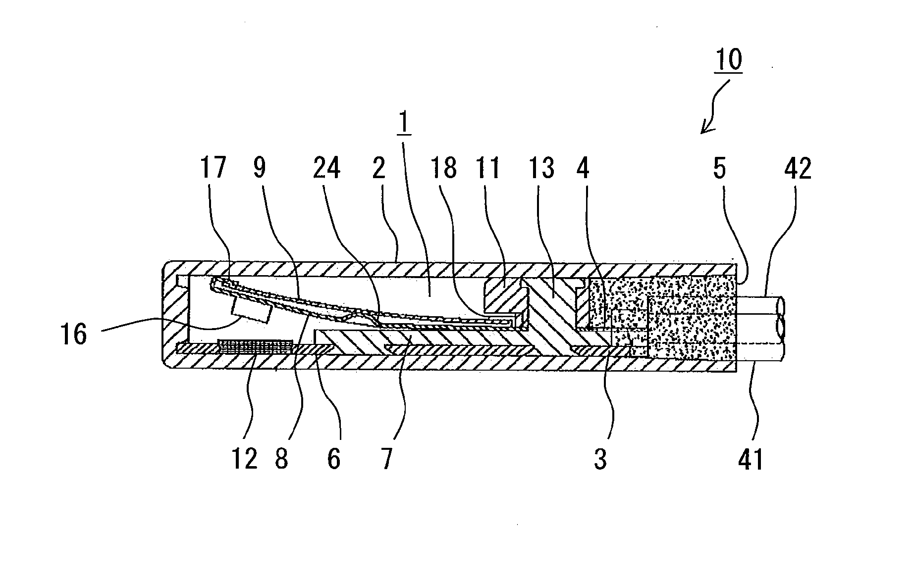
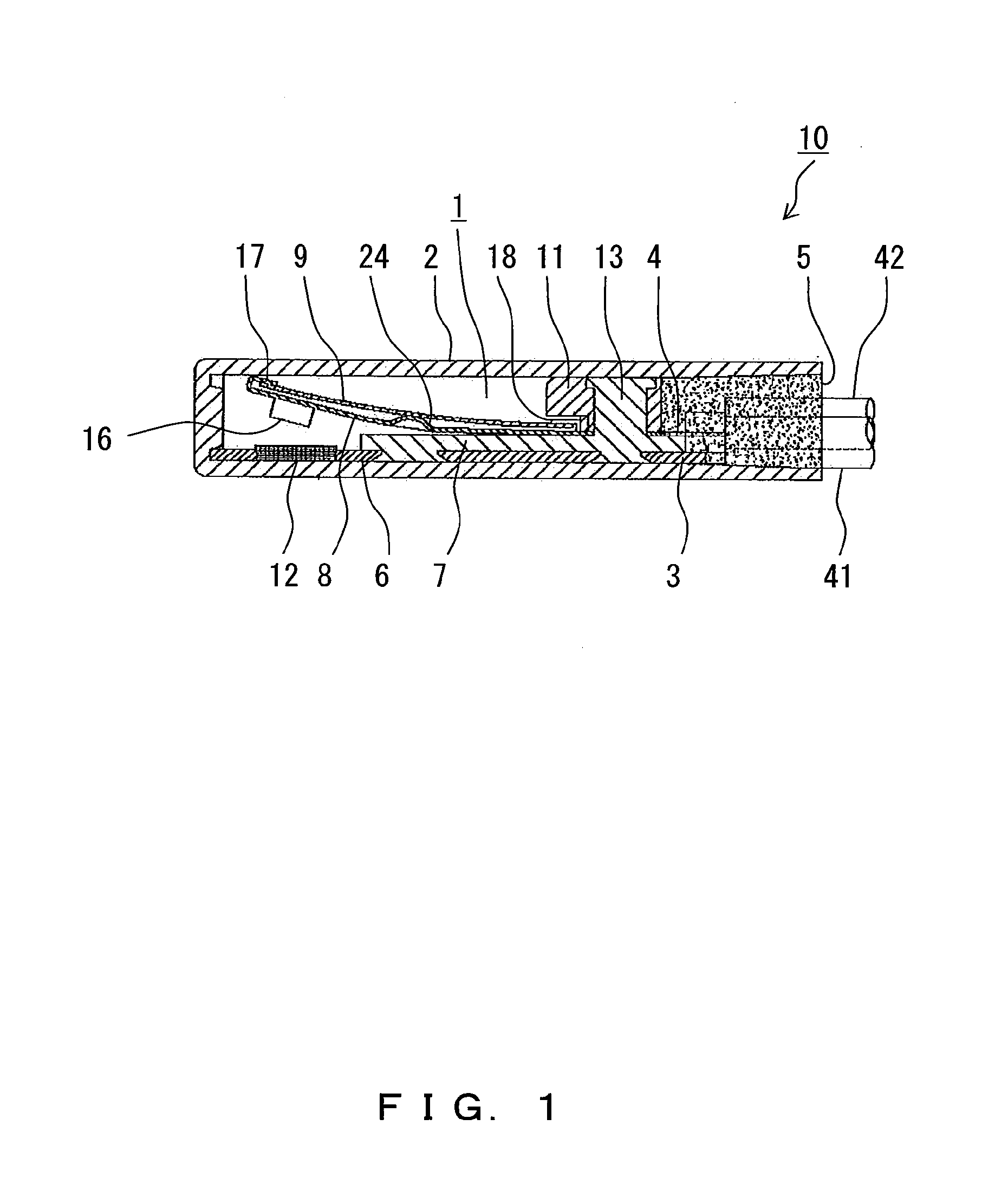
[0074]FIG. 1 is a side cross-sectional view of a thermal switch according to an embodiment 1. In the thermal switch 10 illustrated in FIG. 1, a thermal switch body part 1 is assembled within a parallel-piped insulative housing 2 having one surface that is open (the surface on the right side of FIG. 1).

[0075]The thermal switch body part 1 is sealed within the housing 2 by a sealing member 5, and a first terminal 3 and a second terminal 4 are terminals connected respectively to external connection wires 41 and 42.

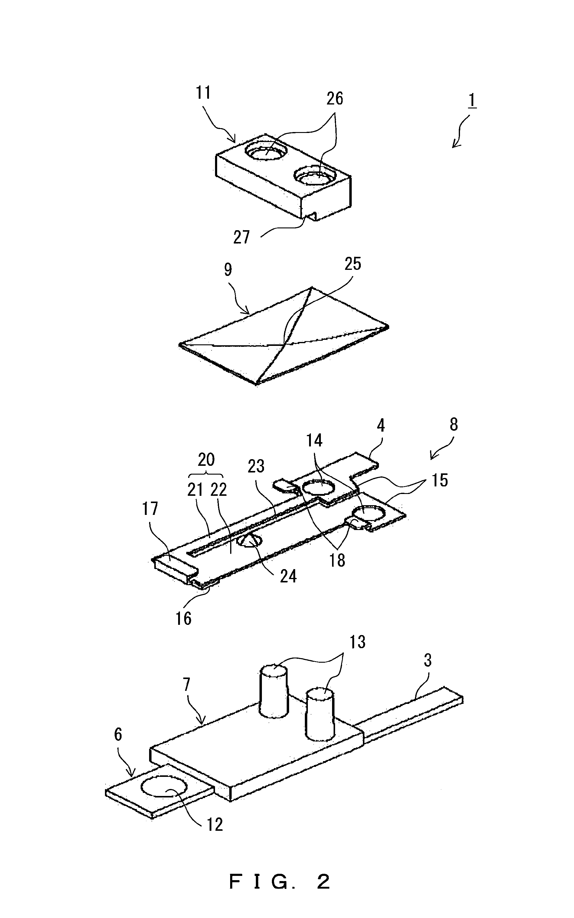
[0076]FIG. 2 is an exploded perspective view of a configuration of the thermal switch body part 1 illustrated by removing the housing 2 and the sealing member 5 of FIG. 1. A configuration of the thermal switch according to this embodiment is described with reference to FIGS. 1 and 2.

[0077]As illustrated in FIGS. 1 and 2, the thermal switch body part 1 is composed of a fixed conductor 6, an insulator 7, a movable plate 8, a bimetal 9 and a resinous block 11.

[0078]The fixed con...

embodiment 2

[0151]FIG. 6 is an exploded perspective view illustrating a configuration of a thermal switch according to an embodiment 2. The same components or functions of FIG. 6 as those of FIG. 2 are denoted with a minimum number of the same reference numerals, needed for descriptions, as those of FIG. 2.

[0152]Unlike the thermal switch 10 illustrated in FIG. 2, the thermal switch 37 illustrated in FIG. 6 is one plate implemented without partitioning the movable plate 8 into the narrow-width part and the wide-width part.

[0153]Even a movable plate in such a shape can be used as a resistive movable plate, namely, a heat-producing resistor by selecting a material with a low conductivity as the material of the movable plate and by increasing an electric resistance, and settings similar to those in the case of the embodiment 1 can be made depending on a current to be processed.

[0154]Note that the movable plate may be implemented as a normal movable plate, and a resistor may be further incorporated ...

embodiment 3

[0155]FIG. 7 is an exploded perspective view illustrating a configuration of a thermal switch according to an embodiment 3. The same components and functions of FIG. 7 as those of FIG. 2 are denoted with a minimum number of the same reference numerals, needed for descriptions, as those of FIG. 2.

[0156]In the thermal switch 38 according to this embodiment, the movable plate 8 of FIG. 2 or 6 is removed, and a bimetal 9 serves as a movable plate, a resistor and a bimetal. Namely, the thermal switch 38 according to this embodiment is an example of a configuration for directly applying a current to the bimetal 9.

[0157]The bimetal 9 in this embodiment has a fixed part 40 provided with holes 39 into which the columns 13 are inserted on the insulator 7.

[0158]Moreover, the bimetal 9 has a second terminal 4, formed in the fixed part 40, for an external connection, and also has a movable contact 16 formed in a position facing the fixed contact 12 of the fixed conductor 6 at an end on a side op...


PUM


Abstract

A movable plate 8 is partitioned by a slim hole 23 into a narrow-width part 21 and a wide-width part 22. When a contact is closed as a thermal switch 10, the narrow-width part 21 produces heat with an applied current branched via a first terminal 3 and a second terminal 4, which short-circuits both ends of the current limit resistor, and the heat of a bimetal 9 is retained with a small amount of local heat to self-hold the non-restoration state, so that the current limit resistor is quickly cooled down. When the power supply switch is turned off, the heat produced by the narrow-width part 21 is quickly cooled down to restore the thermal switch 10 in a short time. Also when the power supply is again turned on in a short time, the current limit resistor is made to function efficiently.

Description

TECHNICAL FIELD[0001]The present invention relates to a thermal switch used in a power supply device for generating a direct-current voltage from an alternating-current power supply.BACKGROUND ART[0002]Power supply devices for generating a predetermined direct-current voltage from an alternating-current power supply are known as conventional techniques. In such power supply devices, a smoothing circuit composed of a large-capacitance capacitor is normally provided on a downstream side of a rectifying element.[0003]To the above described large-capacitance capacitor, a high current caused by an inrush current immediately after power is applied instantaneously flows. This current sometimes reaches approximately several tens of amperes (A) to 100 amperes depending on a condition.[0004]If an inrush current is high as described above, significant ill effects of reducing the lifetime of a power supply switch or a rectifying diode are exerted.[0005]To avoid such ill effects, a current of an...

Claims


Application Information

Patent Timeline
Patent Type & Authority Applications(United States)
IPC IPC(8): H01H37/04
CPCH01H37/002H02H9/001H01H37/5427
Inventor TAKEDA, HIDEAKI
Owner UCHIYA THERMOSTAT
Why Eureka
Try Eureka