
Frequency calibration circuit for automatically calibrating frequency and method thereof

a frequency calibration and frequency technology, applied in the direction of digital transmission, pulse automatic control, electrical apparatus, etc., can solve the problems of increased cost, system vendors often use less accurate non-crystal oscillators, etc., and achieve the effect of simplifying the process of manufacturing and testing chips

Active Publication Date: 2012-01-05
WELTREND SEMICON INC
View PDF2 Cites 11 Cited by
  • Summary
  • Abstract
  • Description
  • Claims
  • Application Information

AI Technical Summary

Benefits of technology

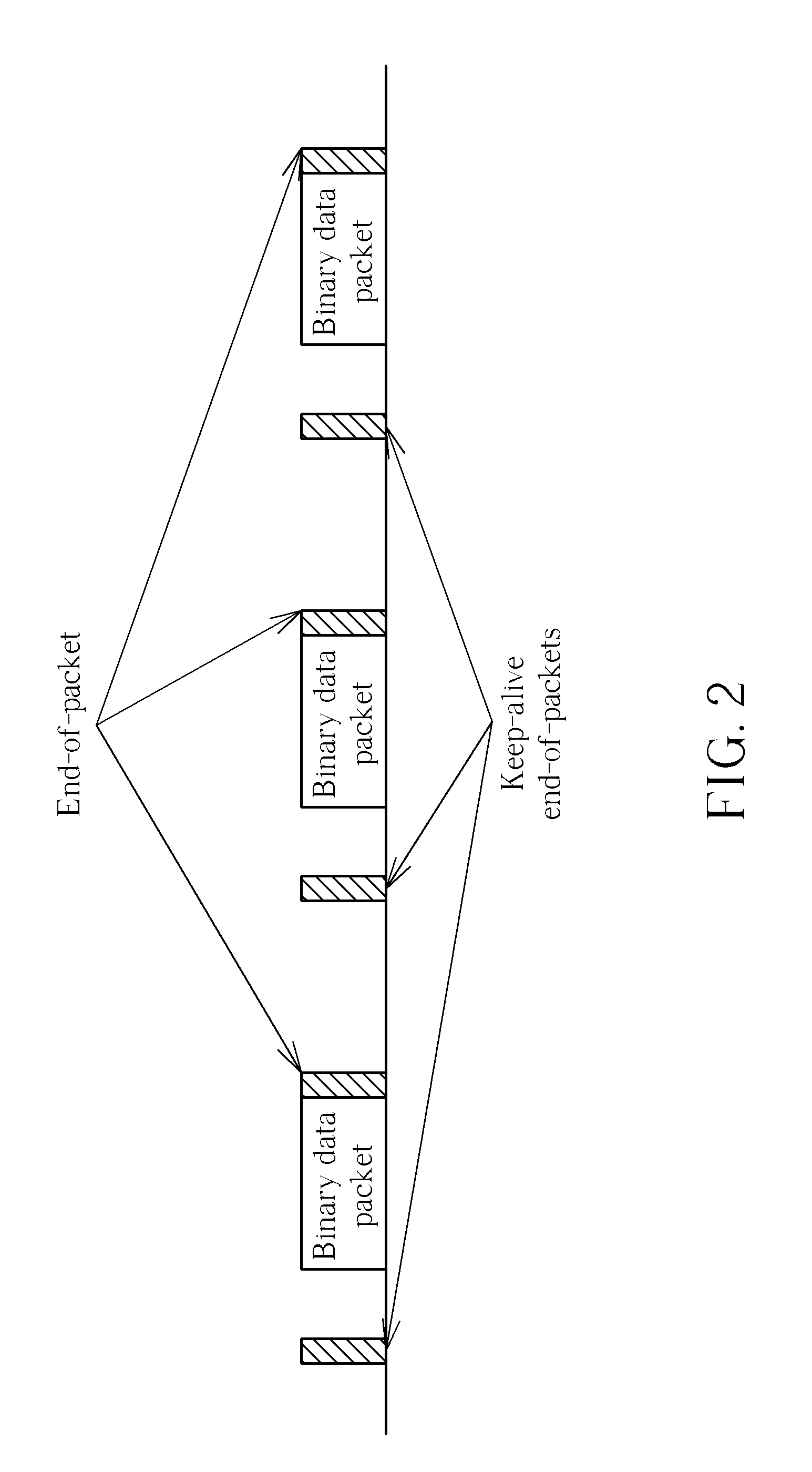
[0009]The present invention provides a frequency calibration circuit for automatically calibrating frequency and method thereof. The frequency calibration circuit for automatically calibrating frequency and method thereof utilize an end-of-packet of a low-speed Universal Serial Bus to calibrate coarsely a frequency of an oscillator, and a SYNC pattern of the low-speed Universal Serial Bus to calibrate finely the frequency of the oscillator. Thus, the present invention may be applied to electronic products without using the non-volatile memory and / or the laser trimming to greatly simplify process of manufacturing and testing chips.

Problems solved by technology

Generally speaking, frequencies generated by crystal oscillators, such as quartz oscillators, are more accurate, but system vendors often use less accurate non-crystal oscillators, such as resistor-capacitor (RC) oscillators, due to lower cost.
However, regardless of whether the corrected parameters are written to the non-volatile memory or the laser-trimming is employed, additional cost is incurred.

Method used


Image

  • Frequency calibration circuit for automatically calibrating frequency and method thereof
  • Frequency calibration circuit for automatically calibrating frequency and method thereof
  • Frequency calibration circuit for automatically calibrating frequency and method thereof

Examples


Embodiment Construction

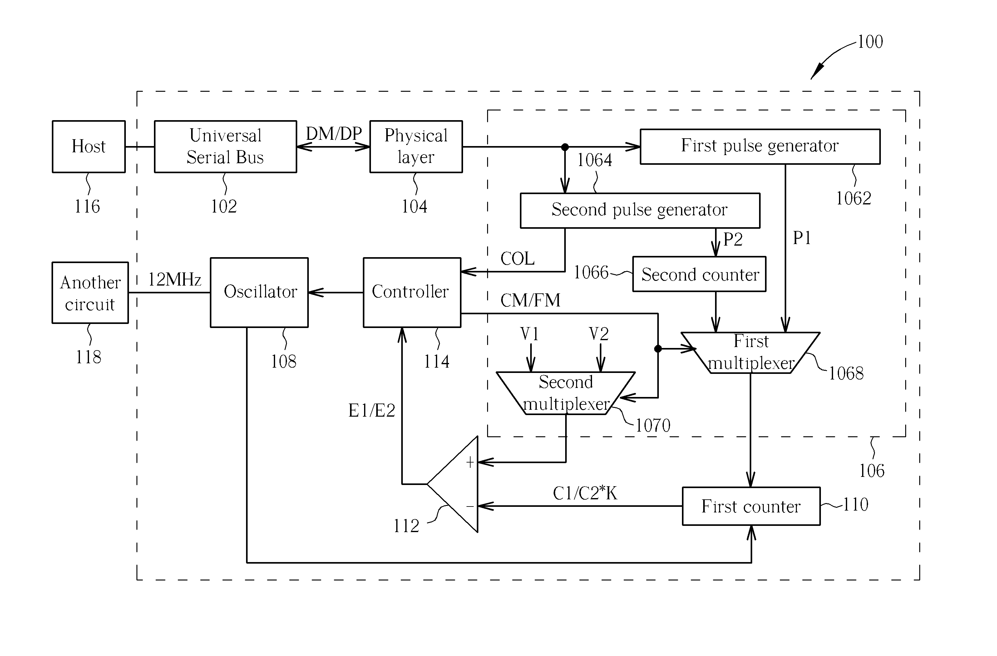
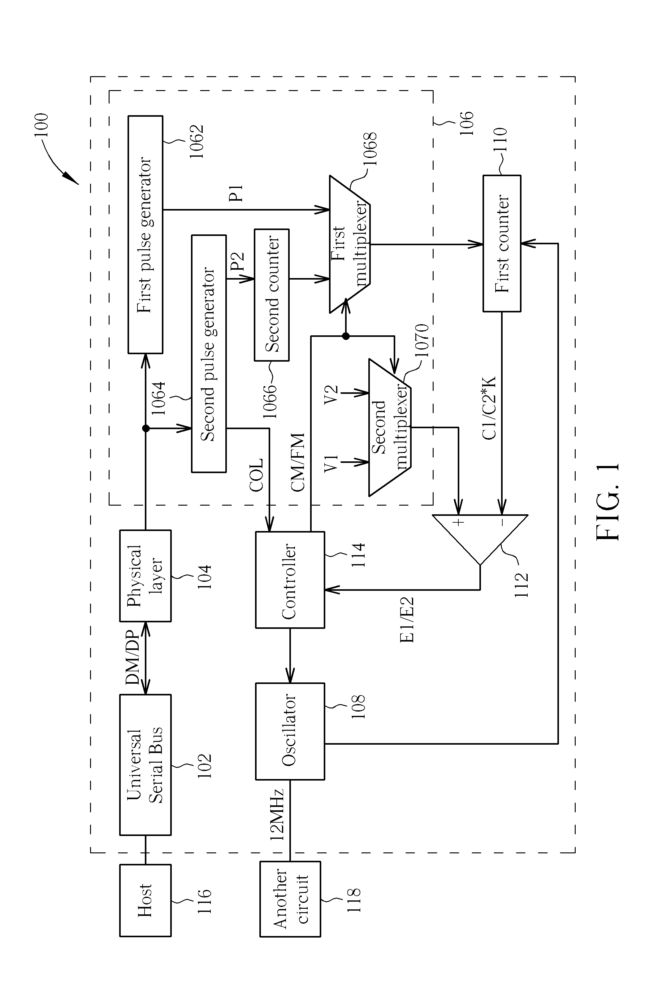
[0018]Please refer to FIG. 1. FIG. 1 is a diagram illustrating a frequency calibration circuit 100 using an end-of-packet (EOP) and a SYNC pattern of a low-speed Universal Serial Bus to calibrate frequency of a resistor-capacitor (RC) oscillator automatically according to an embodiment of the present invention. The frequency calibration circuit 100 includes a Universal Serial Bus 102, a physical layer 104, a pulse generator 106, an oscillator 108, a first counter 110, a comparator 112, and a controller 114. The Universal Serial Bus 102 is used for transmitting a pair of differential signals DM / DP from a host 116 in a low-speed mode. The physical layer (PHY) 104 is coupled to the Universal Serial Bus 102 for converting the pair of differential signals into a series of digital data, where the series of digital data includes a plurality of binary data packets, idle data, and a plurality of keep-alive end-of-packets (EOPs). The pulse generator 106 is coupled to the physical layer 104 fo...


PUM


Abstract

Generate a series of digital data according to a pair of differential signals received from a low speed universal serial bus. Calibrate coarsely a frequency of an oscillator according to a width of an end-of-packet of the series of digital data. And calibrate finely the frequency of the oscillator according to a width of a SYNC pattern of the series of digital data.

Description

CROSS REFERENCE TO RELATED APPLICATIONS[0001]This application claims the benefit of U.S. Provisional Application No. 61 / 359,829, filed on Jun. 30, 2010 and entitled “FREQUENCY CALIBRATION CIRCUIT FOR AUTOMATICALLY CALIBRATING FREQUENCY AND METHOD THEREOF,” the contents of which are incorporated herein by reference.BACKGROUND OF THE INVENTION[0002]1. Field of the Invention[0003]The present invention is related to a frequency calibration circuit for automatically calibrating frequency and method thereof, and particularly to a frequency calibration circuit for automatically calibrating frequency according to an end-of-packet and a SYNC pattern of a low-speed Universal Serial Bus and method thereof.[0004]2. Description of the Prior Art[0005]An oscillator is one component found in many electronic products. Periodic waves generated by oscillators may be employed as carriers in communication systems, as timers or counters in computers or control systems, and as signals with different clock...

Claims


Application Information

Patent Timeline
IPC IPC(8): H04L27/06
CPCH03L7/1077H03L7/085
Inventor HSIAO, FU-YUANPAN, KE-NING
Owner WELTREND SEMICON INC
Learn More