Endpoint control during chemical mechanical polishing by detecting interface between different layers through selectivity change

Inactive Publication Date: 2012-01-05
APPLIED MATERIALS INC
View PDF4 Cites 10 Cited by
  • Summary
  • Abstract
  • Description
  • Claims
  • Application Information

AI Technical Summary

Benefits of technology

[0010]Embodiments described herein relate to removing material from a substrate. More particularly, the embodiments described herein relate to a method of detecting an endpoint for a target substrate during chemical mechanical polishing process. In one embodiment, the method includes polishing one or more reference substrates at a first film removal rate to provide reference spectra, polishing one or more target substrates at a second film removal rate to provide current spectra of the one or more target substrates, wherein the second film removal rate is different from the first film removal rate, identifying an interface transition between different layers formed on the one or more target substrates using a sequence

Problems solved by technology

Integrated circuits have evolved into complex devices that can include millions of components (e.g., transistors, capacitors and resistors) on a single chip.
At sub-micron dimensions, capacitive coupling potentially occurs between adjacent metal interconnects, which may cause cross talk and/or resistance-capacitance (RC) delay and degrade the overall performance of the integrated circuit.
A challenge during CMP is determining whether the polishing process is co

Method used


Image

  • Endpoint control during chemical mechanical polishing by detecting interface between different layers through selectivity change
  • Endpoint control during chemical mechanical polishing by detecting interface between different layers through selectivity change
  • Endpoint control during chemical mechanical polishing by detecting interface between different layers through selectivity change

Examples


Embodiment Construction

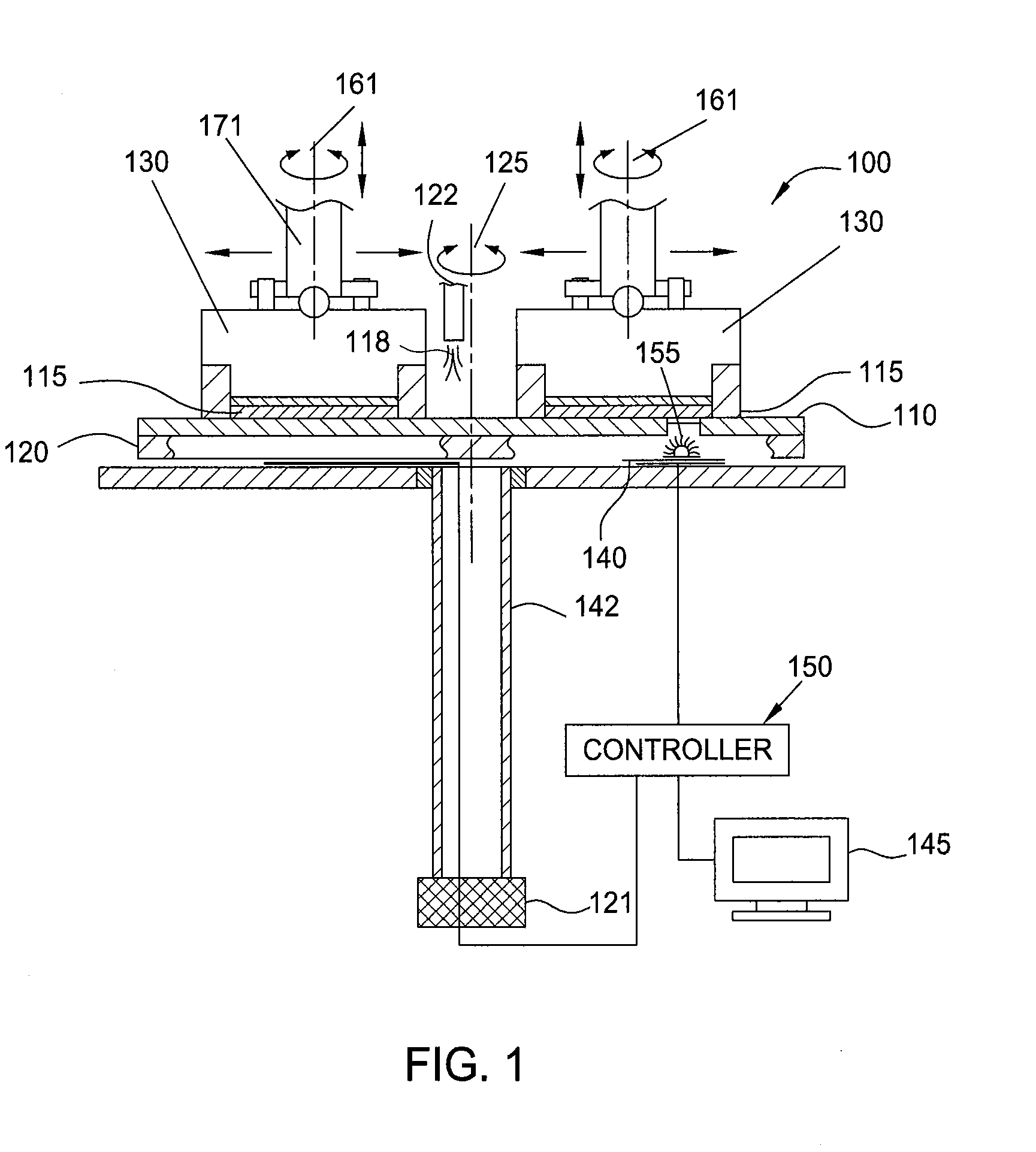
[0022]As discussed previously, variations in the polishing pad condition and the relative speed between the polishing pad and the substrate, etc. can cause variations in the material removal rate. If multiple wafers are to be polished simultaneously, e.g., on the same polishing pad, variations in the initial thickness of the substrate layer, polishing rate variations due to the polishing pad condition, and the relative speed between the polishing pad and the substrate, etc., can lead to the substrates reaching their target thickness at different times. Similarly, if polishing is halted simultaneously for the substrates, then some substrates may not be at the desired thickness. On the other hand, if polishing of the substrates is stopped at different times, then some substrates may have defects and the polishing apparatus will likely be operating at lower throughput.

[0023]As will be discussed below, by identifying interfaces between different layers, from in-situ measurements, a proj...


PUM


Abstract

Embodiments described herein relate to methods of detecting an endpoint for a target substrate during chemical mechanical polishing process. In one embodiment, the method includes polishing one or more target substrates at a first film removal rate to provide reference spectra, polishing one or more target substrates at a second film removal rate to provide current spectra of the one or more target substrates, wherein the second film removal rate is different from the first film removal rate, identifying an interface transition between different layers formed on the one or more target substrates using a sequence of endpoint values obtained based on the reference spectra collected during polishing of the one or more reference substrates, and comparing each current spectrum obtained from current spectra of the one or more target substrates to the reference spectra to obtain the sequence of endpoint values. After identifying the interface transition between different layers formed on the one or more target substrates, the one or more target substrates is optionally overpolished to past a target polishing thickness.

Description

CROSS-REFERENCE TO RELATED APPLICATIONS[0001]This application claims benefit of U.S. provisional patent application Ser. No. 61 / 360,356, filed Jun. 30, 2010, which is herein incorporated by reference.BACKGROUND OF THE INVENTION[0002]1. Field of the Invention[0003]Embodiments described herein relate to removing material from a substrate. More particularly, the embodiments described herein relate to endpoint control during chemical mechanical polishing.[0004]2. Description of the Related Art[0005]Integrated circuits have evolved into complex devices that can include millions of components (e.g., transistors, capacitors and resistors) on a single chip. The demand for greater circuit density necessitates a reduction in the dimensions of the integrated circuit components, e.g., sub-micron dimensions and the use of various materials to fabricate devices in order to achieve much faster and better electrical performance, such as materials with higher conductivity used in metal lines, materi...

Claims


Application Information

Patent Timeline
IPC IPC(8): H01L21/66
CPCB24B37/013H01L22/12H01L2924/0002H01L22/26H01L2924/00H01L21/304
Inventor HU, XIAOYUANWANG, ZHIHONGTU, WEN-CHIANG
Owner APPLIED MATERIALS INC
Why Eureka
Try Eureka