Plasma processing apparatus and plasma processing method

a technology of plasma processing and processing apparatus, which is applied in the direction of coating, chemical vapor deposition coating, metallic material coating process, etc., can solve the problems of high temperature, reduced quality and damage of substrate, and reduced throughpu

Inactive Publication Date: 2012-01-12
PANASONIC INTELLECTUAL PROPERTY MANAGEMENT CO LTD
View PDF8 Cites 386 Cited by
  • Summary
  • Abstract
  • Description
  • Claims
  • Application Information

AI Technical Summary

Benefits of technology

[0009]The three or more plural points of the outer circumferential edge section on the side of the lower surface of the substrate, the three or more plural points being spaced from each other in the circumferential direction, are in contact with the substrate contact sections of the substrate supporting section. In other words, the substrate contained in the substrate containing hole of the tray is not supported in a surface contact mode relative to the substrate supporting section but supported at the plural points on the substrate supporting section in a point contact mode. By supporting in a point contact mode, a contact area between the substrate contained in the substrate containing hole and the substrate supporting section of the tray is small. Thus, heat transfer from the tray to the substrate is suppressed. Therefore, even when the tray is carried out from the chamber after the plasma processing and moved from a vacuum environment to an atmospheric environment, a temperature increase of the substrate (particularly the outer circumferential edge section) due to the heat transfer from the tray can be reduced.
[0026]With the plasma processing apparatus and the plasma processing method of the first to fourth aspects of the present invention, the temperature increase of the substrate due to the heat transfer from the tray after the plasma processing can be reduced. Thus, there is no need for providing a stand-by time for cooling by heat release, heat transfer, or the like, so that throughput can be improved. With the configuration that the substrate contact section of the substrate supporting section of the tray is in contact with the substrate in a point contact or line contact mode or the configuration that the heat transfer material layer is provided on the lower surface of the tray, that is, with the relatively simple configuration, the temperature increase of the substrate due to the heat transfer from the tray after the plasma processing can be reduced. Thus, simplification of the apparatus and cost reduction can be realized.

Problems solved by technology

During the plasma processing, the substrate is cooled due to the heat transfer with the substrate susceptor as described above, whereas the tray is not effectively cooled, and thus has a high temperature.
This temperature increase of the tray after the plasma processing may cause a decrease in quality and damage of the substrate.
Thus, this may cause throughput degradation.
However, provision of this cooling chamber may cause complication of the apparatus and a cost increase.
Therefore, heat transfer efficiency from the tray to the substrate is low.

Method used


Image

  • Plasma processing apparatus and plasma processing method
  • Plasma processing apparatus and plasma processing method
  • Plasma processing apparatus and plasma processing method

Examples


first embodiment

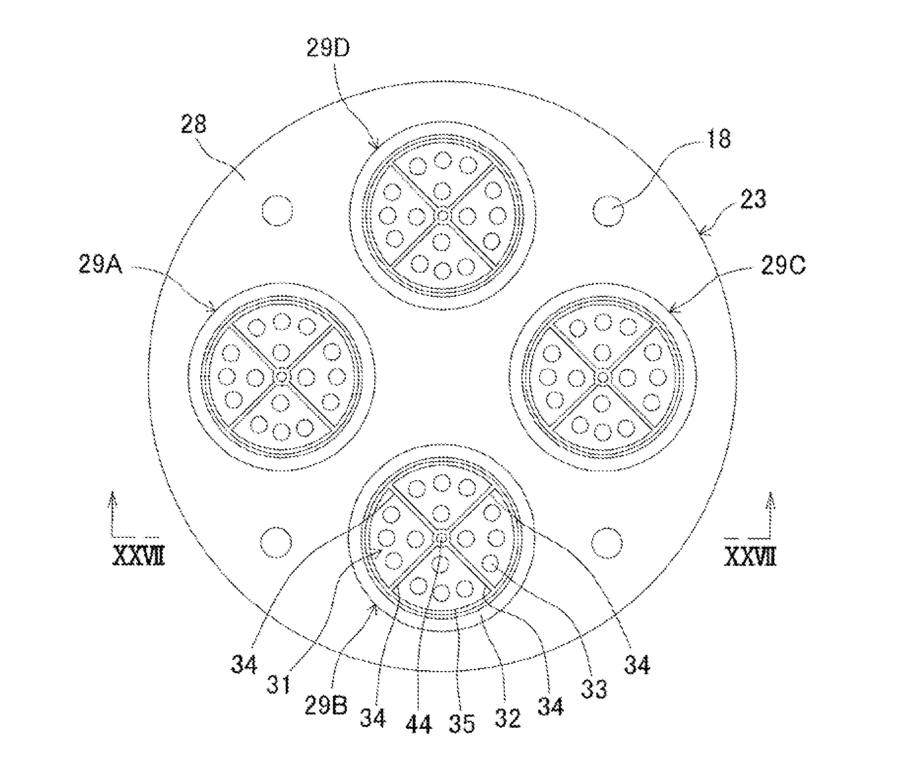
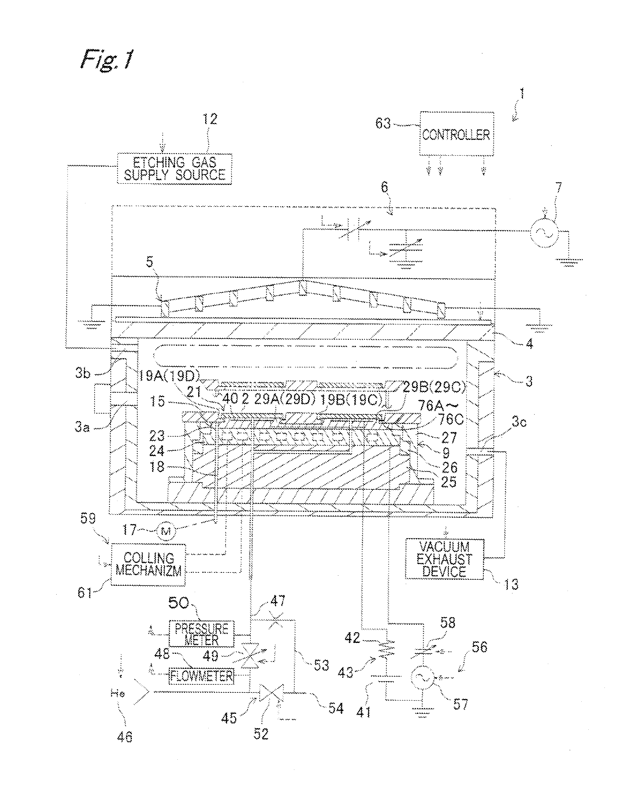
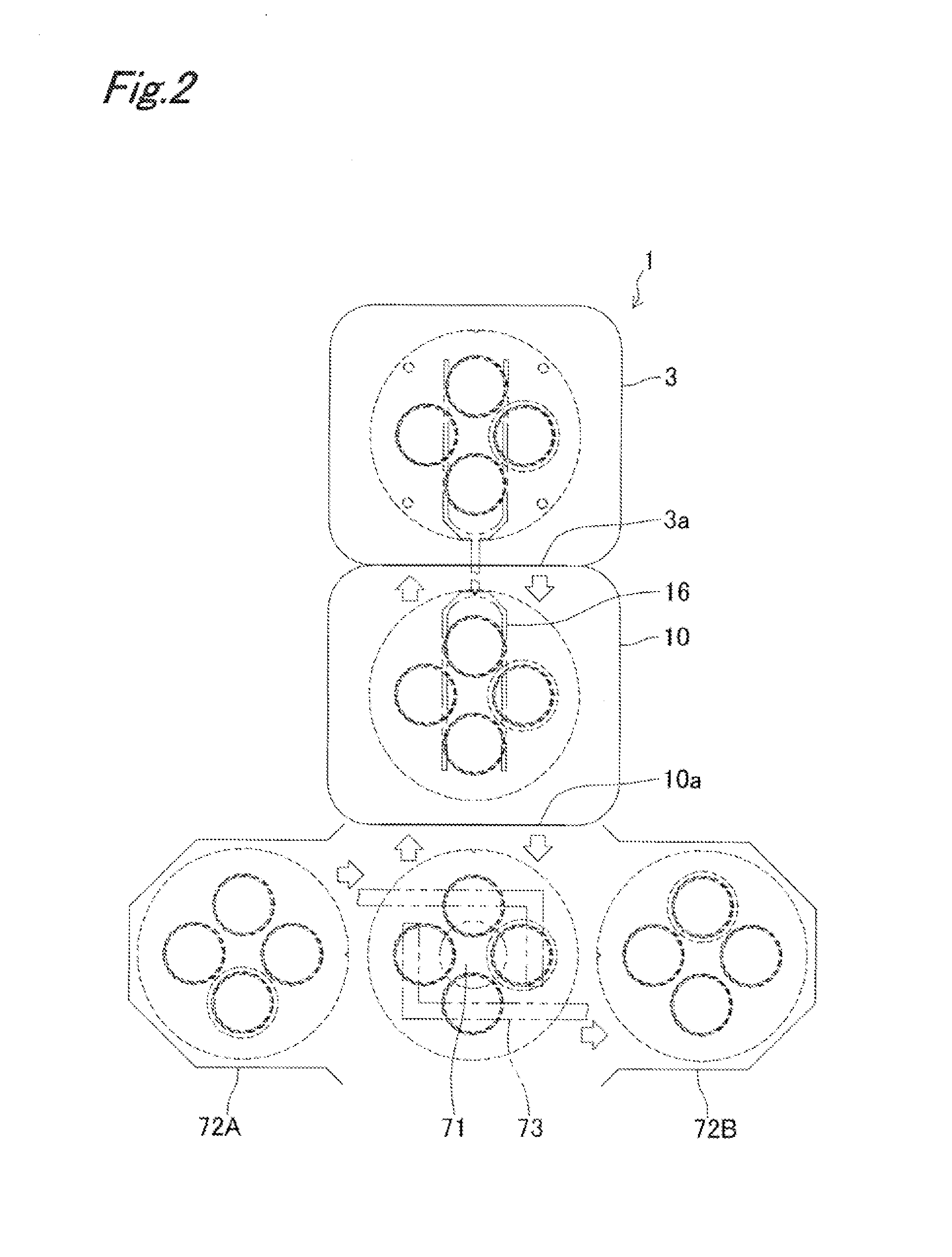
[0084]FIGS. 1 and 2 show an ICP (inductively-coupled plasma) type dry etching apparatus 1 according to a first embodiment of the present invention.

[0085]The dry etching apparatus 1 is provided with a chamber (vacuum chamber) 3 forming an etching chamber (processing chamber) inside which dry etching (plasma processing) is performed to substrates 2, the chamber 3 capable of being decompressed. An upper end opening of the chamber 3 is closed by a top plate 4 formed by a quartz dielectric body or the like in a sealed state. An ICP coil 5 is arranged on the top plate 4. A high frequency power source 7 is electrically connected to the ICP coil 5 via a matching circuit 6. A substrate susceptor 9 having a function as a lower part electrode to which bias voltage is applied and a function as a holding base for the substrates 2 is arranged on the side of a bottom part in the chamber 3 facing the top plate 4. The chamber 3 is provided with an openable and closable carrying gate 3a communicating...

second embodiment

[0130]In a second embodiment of the present invention shown in FIGS. 11 to 15C, instead of providing the protruding sections 76A to 76C for supporting the lower surface 2a of the substrate 2 on the tray 15 in a point contact mode, a polyimide tape 91 is attached to the lower surface 15c of the tray 15. The polyimide tape 91 is attached by one of or both vacuum adhesion and thermocompression bonding. The polyimide tape 91 is provided with a tape base material (heat transfer material layer) 92 made of polyimide, and an adhesive layer 93 formed on one surface of this tape base material 92. In a case of the thermocompression bonding, the adhesive layer 93 is not necessarily provided. Thereby, there are not such problems that the adhesive layer is exfoliated from an edge of the lower surface 15c of the tray 15 to which the polyimide tape 91 is thermocompression bonded in a case where the apparatus is used for a long time. The adhesive layer 93 is put between the lower surface 15c of the ...

third embodiment

[0141]In a third embodiment shown in FIGS. 16 to 20C, support of the substrate 2 on the tray 15 in a point contact mode of the first embodiment (protruding sections 76A to 76C) and the polyimide tape 91 of the second embodiment are both adopted.

[0142]As most clearly shown in FIG. 18B, in the substrate supporting section 21, the protruding sections 76A to 76C are provided on the upper surface 74a of the annular section 74 (provided on the entire circumference of the hole wall 15d) protruding from the side of the lower surface 15c of the tray 15 in the hole wall 15d in each of the substrate containing holes 19A to 19D so as to be spaced from each other at regular angles. These protruding sections 76A to 76C extend over the entire width of the annular section 74, and the upper surfaces 76a are flat surfaces extending in the horizontal direction. The lower surface 2a of the outer circumferential edge section of the substrate 2 contained in each of the substrate containing holes 19A to 1...


PUM

PropertyMeasurementUnit
thicknessaaaaaaaaaa
thicknessaaaaaaaaaa
diametersaaaaaaaaaa

Abstract

Substrates are contained in substrate containing holes which penetrate a tray in the thickness direction. A dielectric plate in a chamber is provided with a tray supporting surface which supports the lower surface of the tray and substrate placing sections which protrude upward, and has an electrostatic chuck electrode therein. The substrate supporting section which supports the substrate contained in the substrate containing holes is provided with a plurality of protruding sections formed at intervals in the circumferential direction of the substrate containing holes. The substrates are supported in point-contact mode by means of the protruding sections.

Description

BACKGROUND OF THE INVENTION[0001]1. Technical Field[0002]The present invention relates to a plasma processing apparatus such as a dry etching apparatus and a CVD apparatus.[0003]2. Description of the Related Art[0004]Japanese Patent Application Laid-Open Publication 2007-109770 discloses a plasma processing apparatus in which a tray containing a substrate in a substrate containing hole passing through in the thickness direction, the tray capable of being carried in and out, is arranged on a substrate susceptor functioning as a lower part electrode, and the substrate is placed on an upper end surface (substrate placing surface) of a substrate placing section of the substrate susceptor brought into the substrate containing hole. The substrate is closely attached onto the substrate placing surface by electrostatic chuck, and a heat transfer gas is charged between the substrate and the substrate placing surface. A cooling mechanism is provided in the substrate susceptor, and the substra...

Claims


Application Information

Patent Timeline
Patent Type & Authority Applications(United States)
IPC IPC(8): H01L21/3065C23C16/50C23C16/503
CPCH01L21/67757H01L21/68735H01L21/68771H01L21/6875H01L21/68742H01L21/3065H01L21/205
Inventor OKITA, SHOGOASAKURA, HIROMI
Owner PANASONIC INTELLECTUAL PROPERTY MANAGEMENT CO LTD
Why Eureka
Try Eureka