Projector and method for controlling the same

a projector and projector technology, applied in the field of projectors, can solve the problems of difficult to realize a projector having brightness high enough for practical use or the same brightness as a conventional projector, and the most dangerous state in terms of safety, so as to achieve the highest brightness and keep safety

Active Publication Date: 2012-01-12
SHARP NEC DISPLAY SOLUTIONS LTD
View PDF6 Cites 10 Cited by
  • Summary
  • Abstract
  • Description
  • Claims
  • Application Information

AI Technical Summary

Benefits of technology

[0013]An object of the present is to provide a projector capable of solving the problems described above and a method for controlling the same. One example of the object is to realize a projector that makes it possible to design a laser output in a wide state of a zoom lens in which the highest brightness can be achieved and that can keep safety over the full range in which the magnification of the zoom lens is changed and that utilizes a laser light source.

Problems solved by technology

Everybody recognizes that the laser light source has a high potential capacity as a light source, but a projector employing the laser light source has not been put into practical use.
This is not only because an inexpensive semiconductor laser emitting green light has not been put into practical use but also because various regulations are required in terms of the characteristics of a laser light source.
For this reason, it is considered to be difficult to realize a projector having brightness high enough for practical use or the same brightness as a conventional projector using a discharge lamp.
In this regard, when the front projection type projector employing a laser light source is used, the most dangerous state as regards safety is considered to be brought about when a human eye comes closest to a projection lens.
It is in the telescopic state in which a laser power density is higher than in the wide state that the laser beam is dangerous for a human eye.
However, this measure cannot make the best use of potential capacity in the wide state in which there is an allowance for the AEL.

Method used


Image

  • Projector and method for controlling the same
  • Projector and method for controlling the same
  • Projector and method for controlling the same

Examples


Embodiment Construction

[0019]Hereinafter, a mode for carrying out the present invention will be described with reference to the drawings.

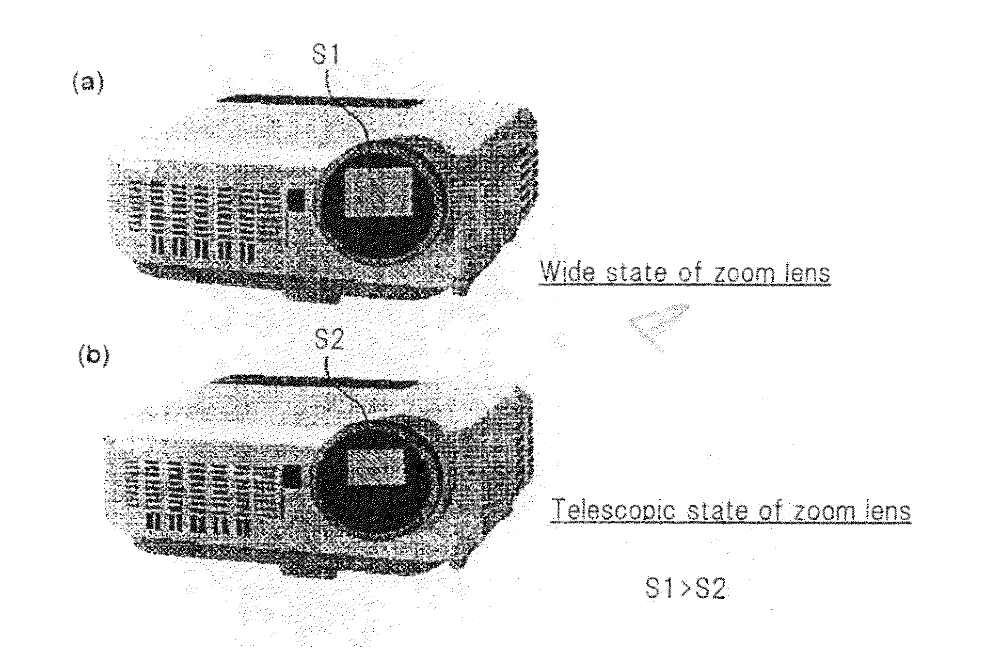
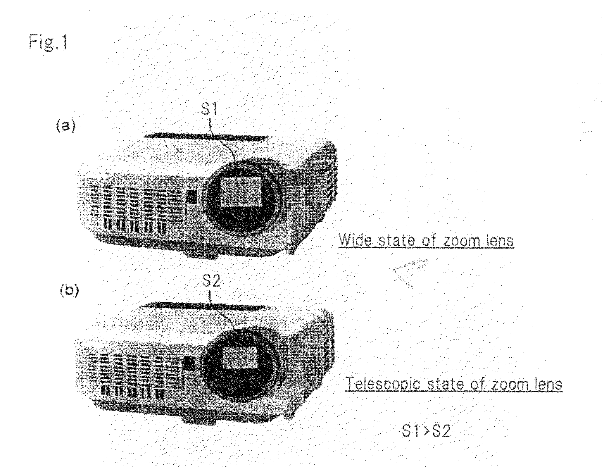
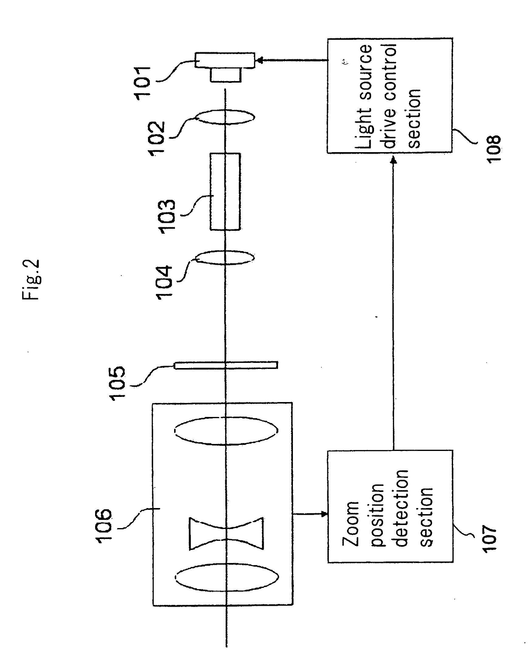
[0020]The present invention relates to a projector that uses a two-dimensional micro-display such as a liquid crystal panel and a DMD as an image modulation device and that applies lights of red (R), green (G), and blue (B) to this image modulation device and that magnifies and projects an image by a projection lens. In particular, the present invention is intended for a projector that has a laser light source as a light source and that has a zoom lens as a projection lens.

[0021]First, the basic concept of the present invention will be described in detail.

[0022]In a case where a laser is used as a light source for a projector in place of an existing discharge lamp, it is a key point in the product competitiveness of the projector how sufficiently practical the projector can be and how high brightness the projector can achieve under conditions that the projector must obse...


PUM


Abstract

There is provided a projector that uses a laser light source and is safe and realizes high brightness. The projector applies a laser beam emitted from a laser light source (101) to an image modulation device (105) and magnifies and projects an image formed in the image modulation device (105) by a zoom lens (106). The projector includes a control mechanism (108) for controlling the amount of energy of the light beam in response to a change in a focal distance of the zoom lens (106) in such a way that an energy density of the laser beam developed on a light emitting surface of the zoom lens (106) is kept at a specified value or smaller than the specified value. The specified value is the energy density of the laser beam in a case where the focal distance of the zoom lens (106) is set to the shortest value and is an accessible emission limit value (AEL value) that satisfies the laser safety class of the projector.

Description

TECHNICAL FIELD[0001]The present invention relates to a projector using a laser light source and to a method for controlling the same.BACKGROUND ART[0002]As to a projector, the research and development of a product using a solid light source in place of a discharge lamp have been actively conducted with the aim of improving performance and reducing size and cost. For example, a rear projection TV and a pocket projector employing an LED light source have been produced on a commercial basis.[0003]As to the solid light source for the projector, a laser light source is regarded as being promising along with an LED. Everybody recognizes that the laser light source has a high potential capacity as a light source, but a projector employing the laser light source has not been put into practical use. This is not only because an inexpensive semiconductor laser emitting green light has not been put into practical use but also because various regulations are required in terms of the characteris...

Claims


Application Information

Patent Timeline
Patent Type & Authority Applications(United States)
IPC IPC(8): G03B21/20G03B21/14
CPCG03B21/2033G03B21/2053H04N9/3197H04N9/3155H04N9/3161G03B2205/0046
Inventor KATOU, ATSUSHI
Owner SHARP NEC DISPLAY SOLUTIONS LTD
Why Eureka
Try Eureka