Cutting Insert and Cutting Edge Replaceable Cutting Tool

a cutting tool and cutting insert technology, applied in the field of cutting insert and cutting edge replaceable cutting tools, can solve the problems achieve the effects of reducing the degree of freedom for designing the cutting tool and insert, reducing the degree of freedom, and enhancing the strength of the inser

Active Publication Date: 2012-01-12
TUNGALOY CORP
View PDF12 Cites 61 Cited by
  • Summary
  • Abstract
  • Description
  • Claims
  • Application Information

AI Technical Summary

Benefits of technology

[0007]The structure for intensifying the strength of the insert as disclosed in Japanese Patent Laid-Open No. 2005-118965 has a constraint that predetermined correlation among such properties as length, width, thickness, and diameter of the center mounting hole of the insert is required to

Problems solved by technology

The structure for intensifying the strength of the insert as disclosed in Japanese Patent Laid-Open No. 2005-118965 has a constraint that predetermined correlation among such properties as length, width, thi

Method used


Image

  • Cutting Insert and Cutting Edge Replaceable Cutting Tool
  • Cutting Insert and Cutting Edge Replaceable Cutting Tool
  • Cutting Insert and Cutting Edge Replaceable Cutting Tool

Examples


first embodiment

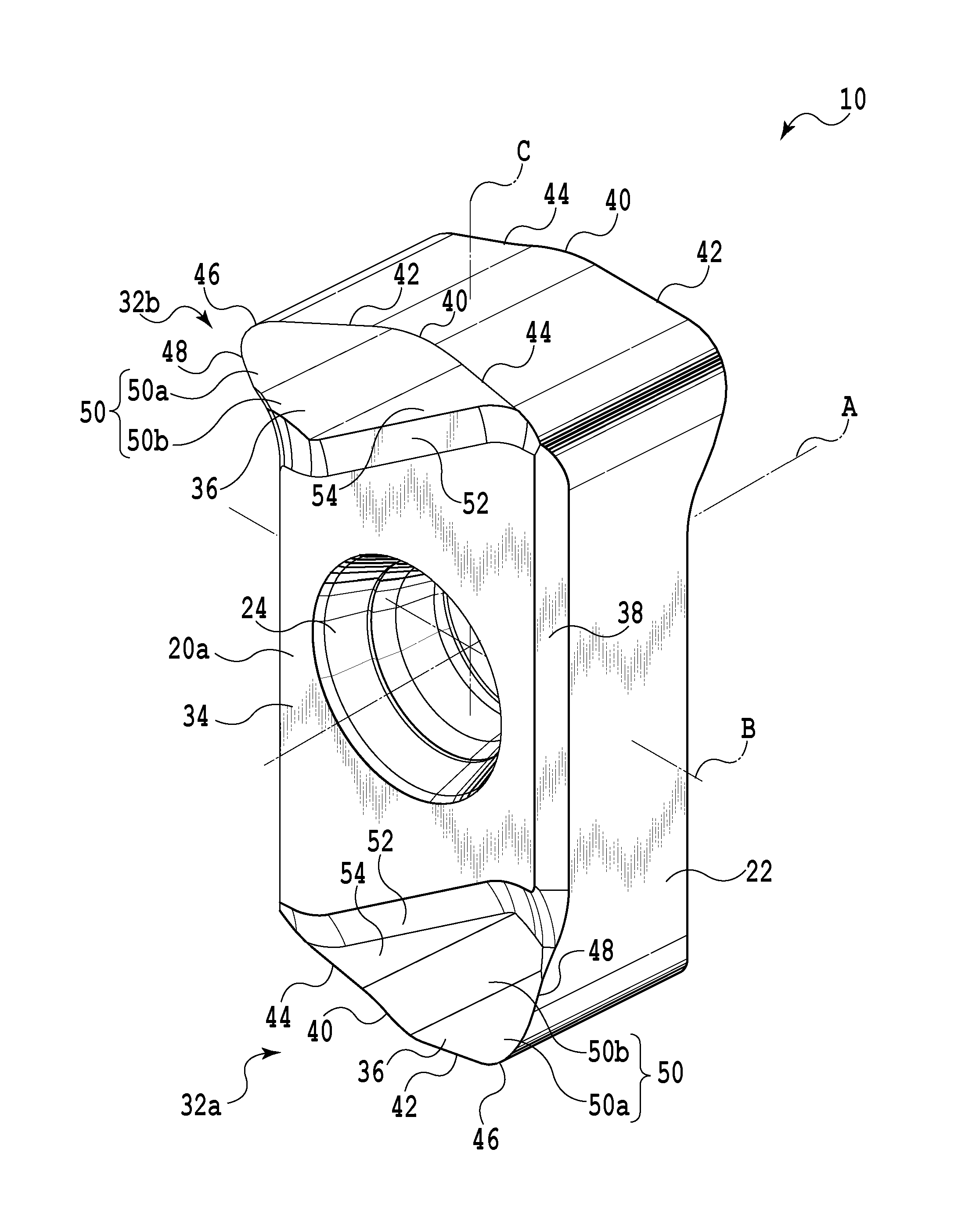
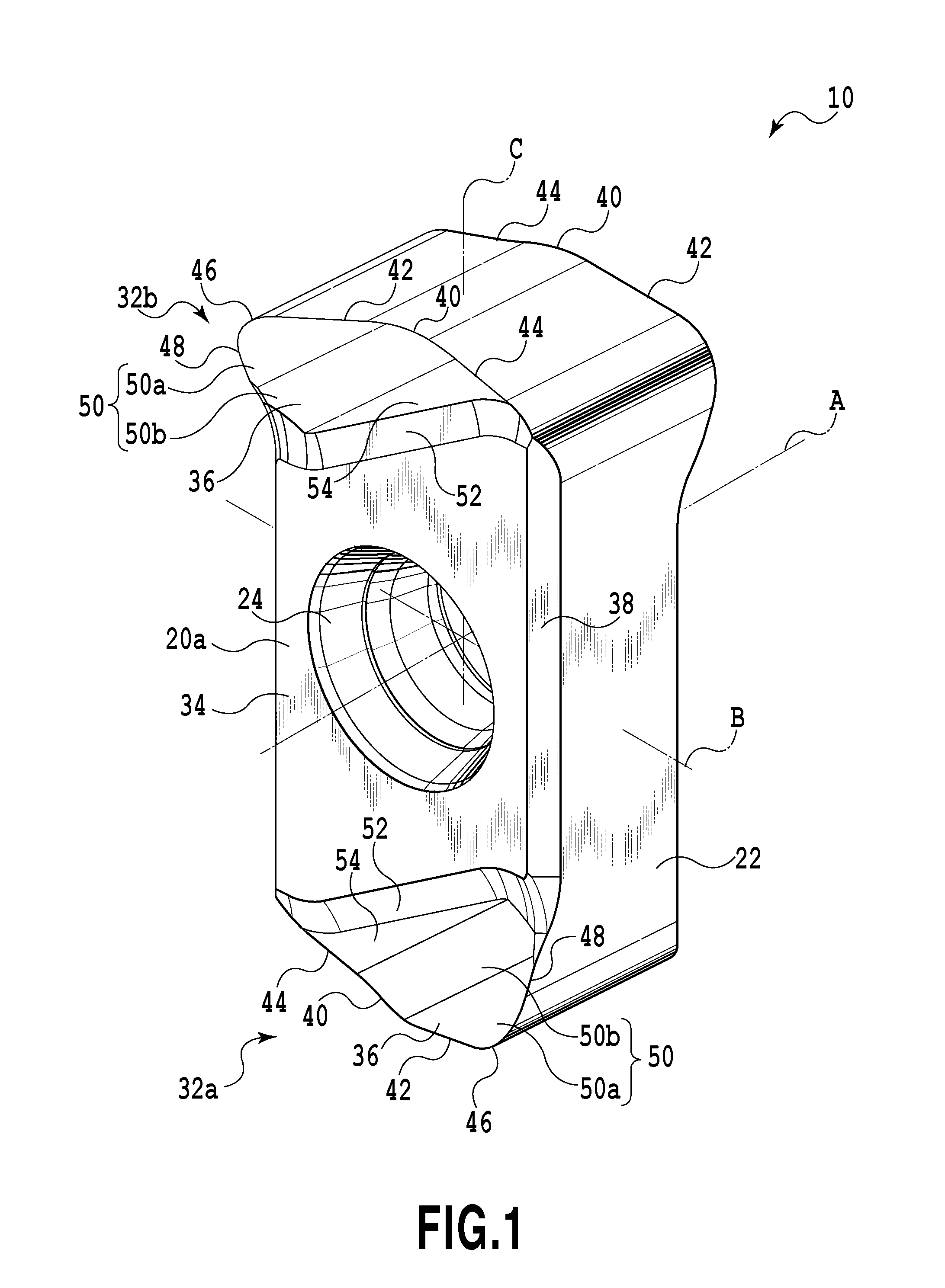
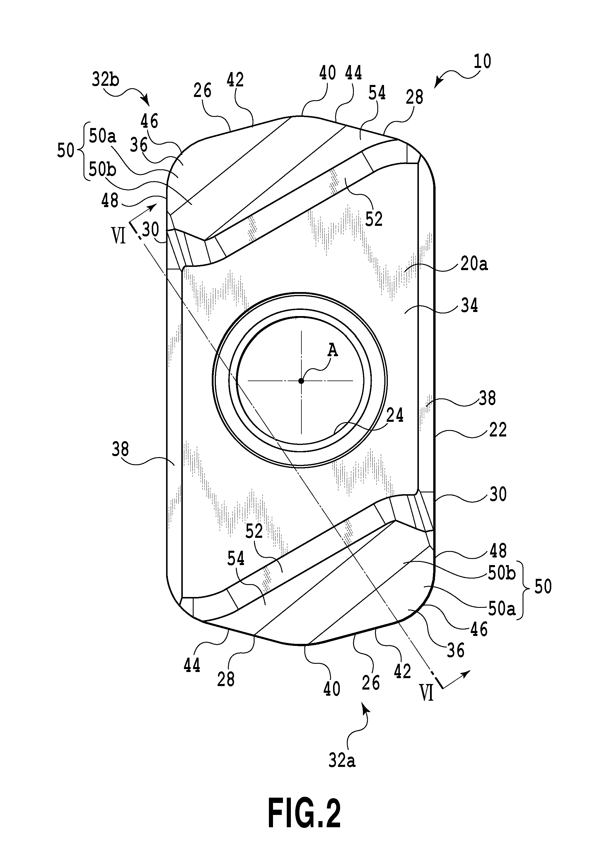
[0038]The cutting insert 10 is structured to be reversibly attached to the end mill body 12 while having both surfaces available, that is, so called the insert with negative configuration. The cutting insert 10 has substantially a hexagonal flat-plate shape. The cutting insert 10 comprises two opposed end surfaces 20, which are a first end surface 20a and a second end surface 20b, and a peripheral side surface 22 which extends between those end surfaces 20a and 20b. A mounting hole 24 which pierces the cutting insert 10 in the thickness direction, that is, pierces between the first end surface 20a and the second end surface 20b is formed in the cutting insert 10. It should be noted that the cutting insert 10 may be formed of a cemented carbide, cermet, ceramics and the like, and in this case, it is formed of the cemented carbide.

[0039]The first end surface 20a has the same shape as that of the second end surface 20b. Those first end surface 20a and second end surface 20b have rotat...

second embodiment

[0089]A cutting insert 100 according to the present invention, which has a structure different from that of the cutting insert 10 will be described referring to FIGS. 15 to 18. The difference between the cutting inserts 10 and 100 will be mainly described hereinafter. The same components of the cutting insert as those of the cutting insert 10 will be designated with the same reference numerals, and the same explanations, thus, will be omitted. The cutting insert 100 may be changed likewise the cutting insert 10 within a range with consistency so as to provide the same effects as those derived from the cutting insert 10.

[0090]The cutting insert 100 has a convex portion 102 at the chip breaker 36. Especially as shown in FIGS. 17 and 18, the convex portion 102 is formed on the bottom portion 54 for controlling the chips flowing from the first minor cutting edge 44. The convex portion 102 is formed to rise from the bottom portion 54 in the direction of the axis A of the cutting insert 1...


PUM

PropertyMeasurementUnit
Angleaaaaaaaaaa
Distanceaaaaaaaaaa

Abstract

A cutting insert includes two end surfaces each having a main surface usable as an attachment surface to a tool body, a peripheral side surface extending between the two end surfaces and a plurality of cutting edge portions each formed at an intersection between each end surface and the peripheral side surface. Each cutting edge portion includes a corner edge formed at a corner of a related end surface, a major cutting edge extending from one end of the corner edge and extending so as to depart from an intermediate plane defined to be perpendicular to the first axis and to include the second axis, and a minor cutting edge extending from the other end of the corner edge and extending in a direction to approach the intermediate plane.

Description

CROSS-REFERENCE TO RELATED APPLICATIONS[0001]This is a Continuation of International Patent Application No. PCT / JP2010 / 056016, filed Apr. 1, 2010 and published as WO 2010 / 114094 on Oct. 7, 2010, which claims priority to Japanese Patent Application No. 2009-089734, filed Apr. 2, 2009. The contents of the aforementioned applications are incorporated by reference in their entirety.BACKGROUND OF THE INVENTION[0002]1. Field of the Invention[0003]The present invention relates to a cutting insert serving as an edge portion attached to a tool body for cutting work, and a cutting edge replaceable cutting tool using the cutting insert, and more particularly relates to a cutting insert which may be used for high-feed working, and a cutting edge replaceable cutting tool using the cutting insert.[0004]2. Description of the Related Art[0005]A cutting edge replaceable end mill has been generally employed as the tool used for cutting work of a die or the like, in which a cutting insert is attached ...

Claims


Application Information

Patent Timeline
IPC IPC(8): B23B27/16B23B27/22
CPCB23C5/109B23C5/207B23C2200/085B23C2200/205B23C2210/0442B23C2210/045Y10T407/235B23C5/20B23C2200/203Y10T407/2274Y10T407/2202Y10T407/23B23C2210/0457B23C5/202B23C5/22B23C5/10B23B27/16
Inventor SAJI, RYUICHI
Owner TUNGALOY CORP
Why Eureka
Try Eureka