
Engine Flushing System

a technology of engine flushing and components, applied in the direction of propulsive elements, marine propulsion, vessel construction, etc., can solve the problems of engine failure, engine failure, engine shutdown, etc., and achieve the effect of quick, effective removal and increased flushing

Inactive Publication Date: 2012-01-12
HOWARD MARTIN
View PDF13 Cites 6 Cited by
  • Summary
  • Abstract
  • Description
  • Claims
  • Application Information

AI Technical Summary

Benefits of technology

"The invention is a system and method for flushing the cooling system of an outboard marine motor quickly and effectively. The system can be attached to the power head of the motor and uses a downward flow of water to flush the engine. The flushing apparatus includes a hose, fittings, and a garden hose, which can be reattached for further flushing. The system allows for quick and easy flushing of the engine while it is off. The technical effects of the invention include improved engine performance and efficiency, reduced maintenance costs, and improved user experience."

Problems solved by technology

In any engine-driven mechanical device, heat generated by the components can pose serious problems to the engine.
Overheating of the engine can cause the engine to fail, either rendering the engine temporarily out of commission, or in a worst case scenario, completely destroying the engine.
While water helps keep the internal components of the engine cool, the water being drawn through can contain many harmful, corrosive materials.
Salt water, especially salt water with a high salinity level, is very corrosive and can cause severe damage to the components inside of the marine motor.
If the salt water is left inside for too long, many motors become completely inoperative, and the motor would have to be replaced.
A disadvantage of traditional engine flushing systems is that they cannot get enough water into the motor block to properly flush the engine.
This allows the matter and particulate to build up over time, decreasing the life of the motor.
Another disadvantage of traditional engine flushing systems is that fresh water never reaches the power heads, where it is needed the most, since the traditional devices work by covering the intake vents in the lower end.
Another disadvantage of traditional engine flushing systems is that overheating is possible as it may be necessary to run the engine during the operation.
Engine overheating is extremely harmful to the motor's life, and may cause immediate and permanent damage to the motor.
Another disadvantage of traditional engine flushing systems is that it is often ineffective, resulting only in the relocation of salt, minerals, and organic residues from one location inside the motor to another location, rather than expelling the matter.
Another disadvantage of traditional engine flushing systems is that it is time consuming, requiring a relatively long amount of time to perform a fairly ineffective flushing.
Another disadvantage of traditional engine flushing systems is that the system cannot deliver enough volume of water to properly flush the engine.
Another disadvantage of traditional engine flushing systems is that the system may be difficult to operate, and it can be difficult to attach the hose.
It is very dangerous to hang over the stern of the boat to hold the muffs in place while flushing the marine engine for a minimum of 15 minutes.
Another disadvantage of traditional engine flushing systems is that the engine may need to be operated while the flushing occurs.
This decreases the overall life of the engine, and can be very noisy to the person operating the flushing system.

Method used


Image

  • Engine Flushing System
  • Engine Flushing System
  • Engine Flushing System

Examples


Embodiment Construction

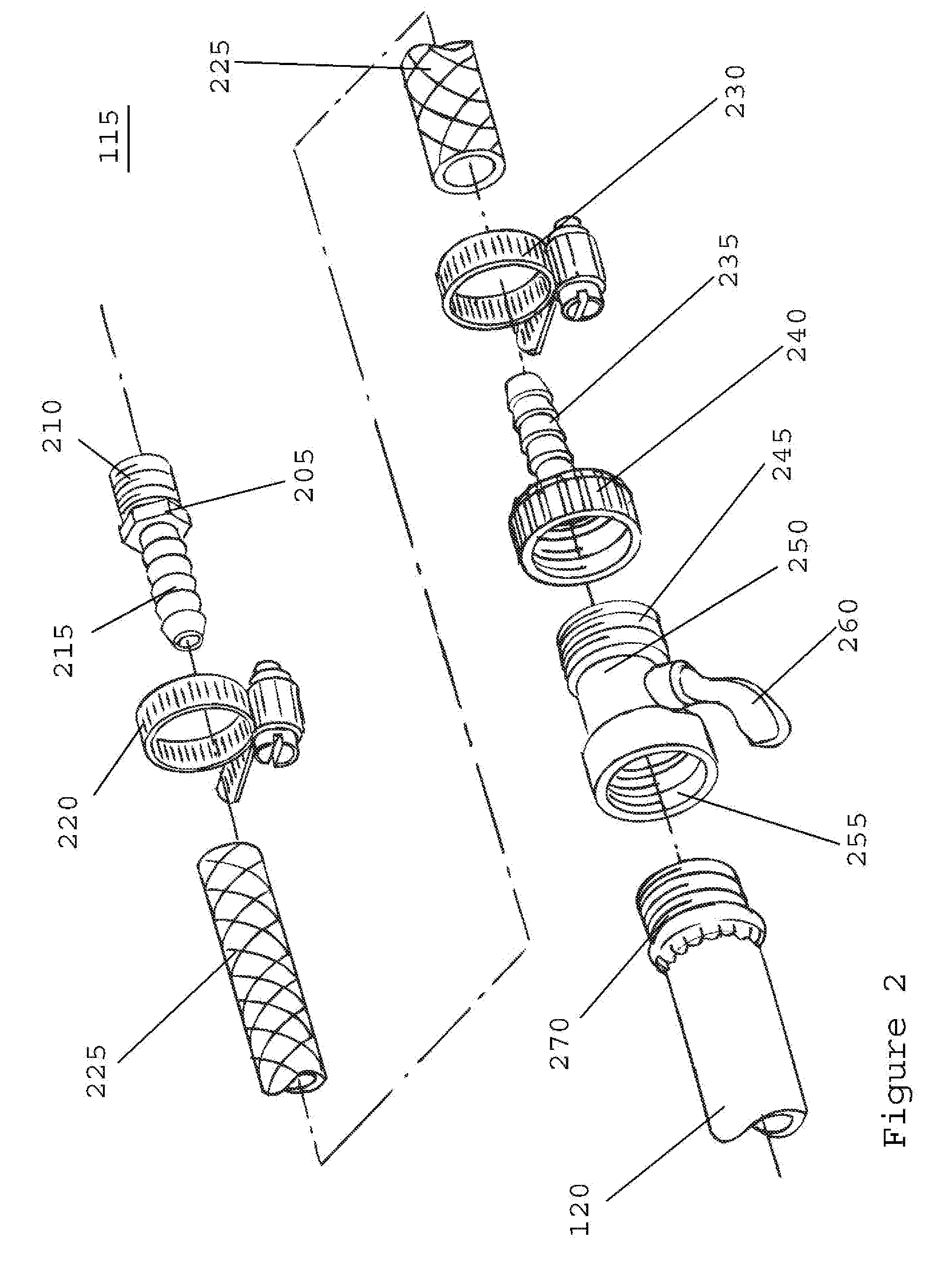
[0026]The exemplary embodiments of the present invention may be further understood with reference to the following description and the related appended drawings, wherein like elements are provided with the same reference numerals. The exemplary embodiments of the present invention are related to an apparatus for flushing an outboard engine. Specifically, the apparatus attaches to an upper portion of the power head of the engine and flushes the internal cooling components of the engine. The exemplary embodiment is described with reference to an outboard motor, but those skilled in the art will understand that the present invention may be implemented on any motor that requires flushing of the internal passages of the cooling system.

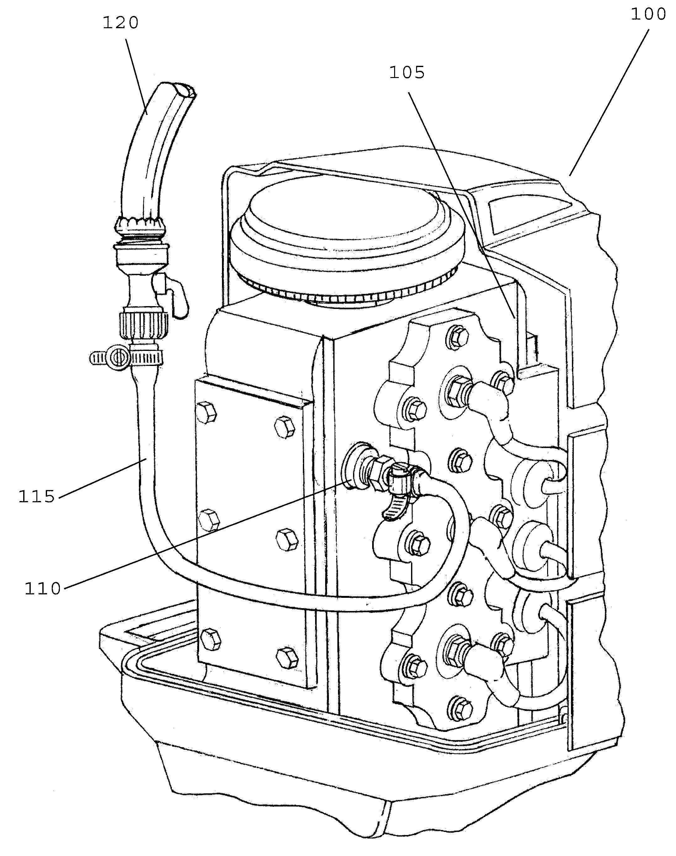
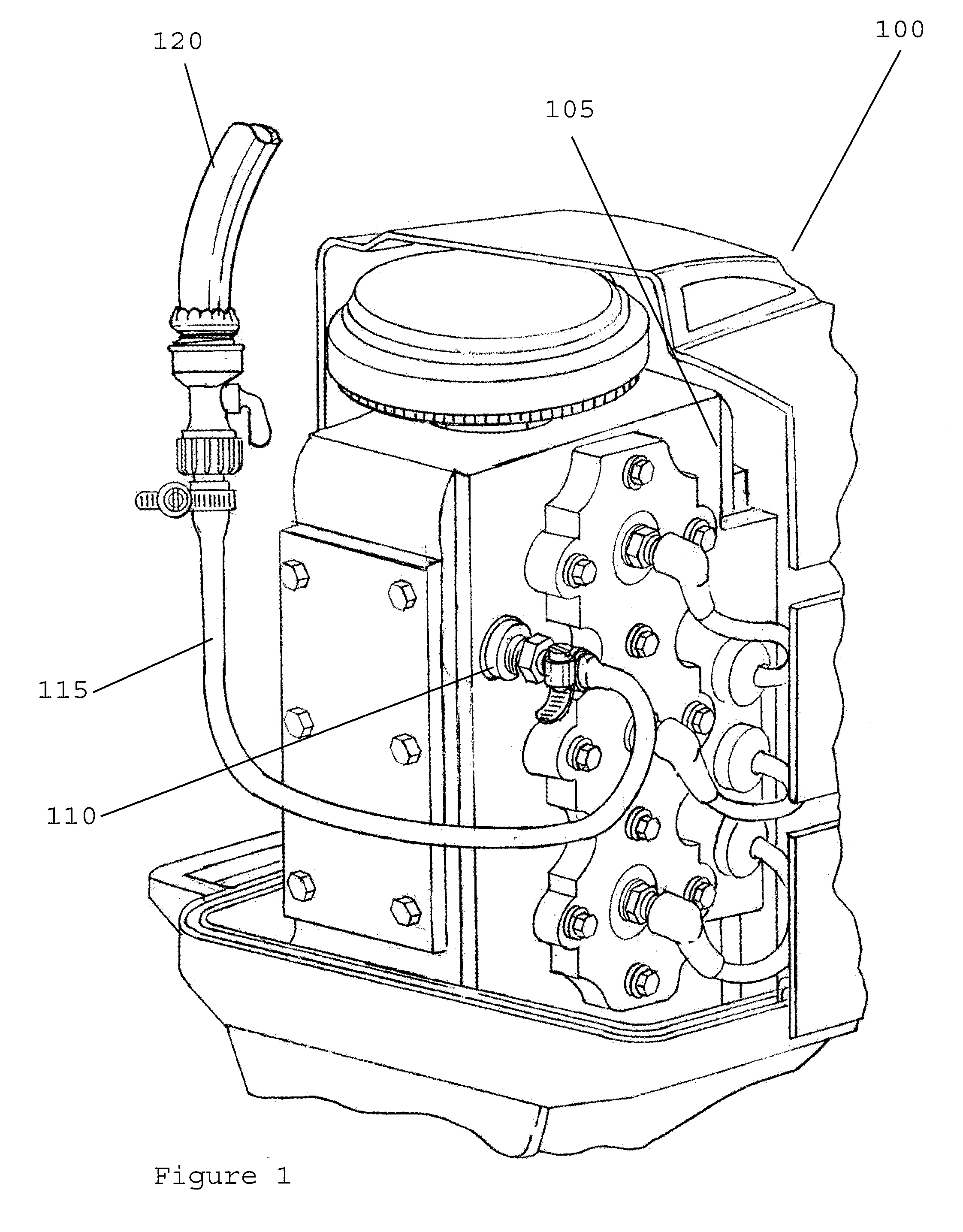
[0027]As best seen in FIG. 1, a perspective view of an engine flushing apparatus 115 attached to an outboard marine engine 100 is shown. Marine engine 100 is a standard outboard engine with a tapping access plug 110 on the power head 105 of the engine. Engi...


PUM


Abstract

A method of flushing internal water passages of a motorboat engine having the steps of attaching a water supply to a power head of the motorboat engine and flushing the internal water passages of the motorboat engine using a water flow which flows in a substantially downward direction after the water enters the motorboat engine.

Description

CROSS-REFERENCE TO RELATED APPLICATIONS[0001]The present application claims the benefit under 35 U.S.C. §119(e) of U.S. Provisional Patent Application Ser. No. 61 / 362,022 filed on Jul. 7, 2010.FIELD OF THE INVENTION[0002]The present application relates generally to the field of engine flushing systems, and more specifically, relates to a fresh water flushing system for cleaning the internal passages of a cooling system of a marine outboard engine.BACKGROUND OF THE INVENTION[0003]In any engine-driven mechanical device, heat generated by the components can pose serious problems to the engine. Overheating of the engine can cause the engine to fail, either rendering the engine temporarily out of commission, or in a worst case scenario, completely destroying the engine. To combat heat in an engine, cooling systems are used to cool down the components. In a car, a coolant reservoir, such as water, is contained in the car, and is drawn through the engine block to cool the components. In a ...

Claims


Application Information

Patent Timeline
Patent Type & Authority Applications(United States)
IPC IPC(8): B63H21/38
CPCB63H21/38
Inventor HOWARD, MARTIN
Owner HOWARD MARTIN
Learn More