
Method and facility system for providing an energy carrier by application of carbon dioxide as a carbon supplier of electric energy

a technology of electric energy carrier and facility system, which is applied in the field of facility system for providing an energy carrier by application of carbon dioxide as a carbon supplier of electric energy, can solve the problems of significant increase in the cost of power generation with wind or solar power plants, and increase in the cost of power generation with these facilities. , the effect of reducing the cost of the plant, and reducing the cos

Active Publication Date: 2012-01-12
SILICON FIRE AG
View PDF3 Cites 13 Cited by
  • Summary
  • Abstract
  • Description
  • Claims
  • Application Information

AI Technical Summary

Benefits of technology

"The invention provides a method for generating storable and transportable energy carriers using renewable energy sources, such as wind and solar power, with low emissions of CO2. The method involves a chemical process where carbon dioxide gas is utilized and hydrogen is generated through an electrolysis process. The generated energy carriers can be used in a variety of applications, such as fuel cells and combustion engines. The invention also includes a facility system that is operated as a constant and long-term as possible, with the addition of regenerative power from a mixed network. The use of regenerative power is optimized to minimize CO2 emissions and increase energy conversion efficiency. The invention also simplifies the regulation and control of the power supply, making it easier for operators to manage. Overall, the invention provides a method and system for generating energy carriers using renewable energy sources in a sustainable and cost-effective way."

Problems solved by technology

Wind and solar power plants which convert the renewable energies into electric energy have an unsteady delivery of power, which hampers the operation of a facility according to the requirements of an electrically mixed network and gives rise to facility and operation costs for additional reserve and frequency regulation facilities.
Accordingly, the costs of power generation from wind or solar power plants are thereby raised significantly compared to conventional power.
It is seen as a problem that at present almost all regenerative electric energy that is produced is supplied to the public AC voltage mixed network, the frequency of which is allowed to vary only within very narrow boundaries (e.g., + / −0.4%).
The necessity that wind and solar power plants must always hold available the sufficient reserve and frequency regulation capacities leads to an increase in the costs of power generation with these facilities.
Wind and solar power plants within the electrical mixed network thus result in further “hidden” costs and problems.
Already at the present stage of completion of wind power plants in many countries, the electric power supply network may create serious problems, if, e.g., as a result of wind scarcity or strong winds, wind power fails at a large scale, in particular if this failure occurs suddenly or unexpectedly.
It follows from the above that solar and wind power plants which supply (current) into an electrical mixed network can hardly replace the installed outputs of other power plants in the mixed network.
This leads to a situation that solar and wind power may be valuated approximately only with the saved fuel cost of the other heat power plants present in the network.

Method used


Image

  • Method and facility system for providing an energy carrier by application of carbon dioxide as a carbon supplier of electric energy
  • Method and facility system for providing an energy carrier by application of carbon dioxide as a carbon supplier of electric energy
  • Method and facility system for providing an energy carrier by application of carbon dioxide as a carbon supplier of electric energy

Examples


Embodiment Construction

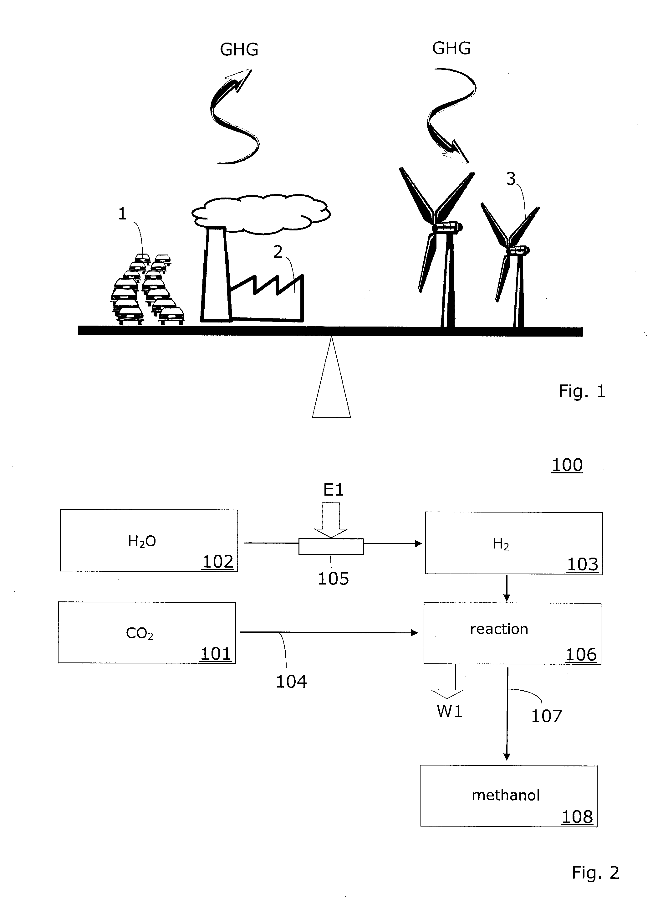
[0036]The method according to the invention is based on a new concept, which by using available starting materials provides so-called reaction products that are either directly usable as an energy carrier or that are indirectly usable as energy carriers, i.e. after performing additional intermediate steps.

[0037]The term energy carrier is used herein to designate compounds, which may either be used directly as a fuel or combustion material (such as, e.g., methanol 108) and also compounds (such as, e.g., silicon 603), which have an energy content or an elevated energy level and which can be converted in further steps with delivery of energy (refer to energy E3 in FIG. 6) and / or with delivery of a further energy carrier (such as, e.g., hydrogen 103).

[0038]The transportability of the energy carrier is herein characterized by the chemical reaction potential.

[0039]In the case of hydrocarbons (such as methanol 108) being used as an energy carrier, specific framework conditions should be re...


PUM

PropertyMeasurementUnit
electric energyaaaaaaaaaa
electric direct current energyaaaaaaaaaa
direct current energyaaaaaaaaaa

Abstract

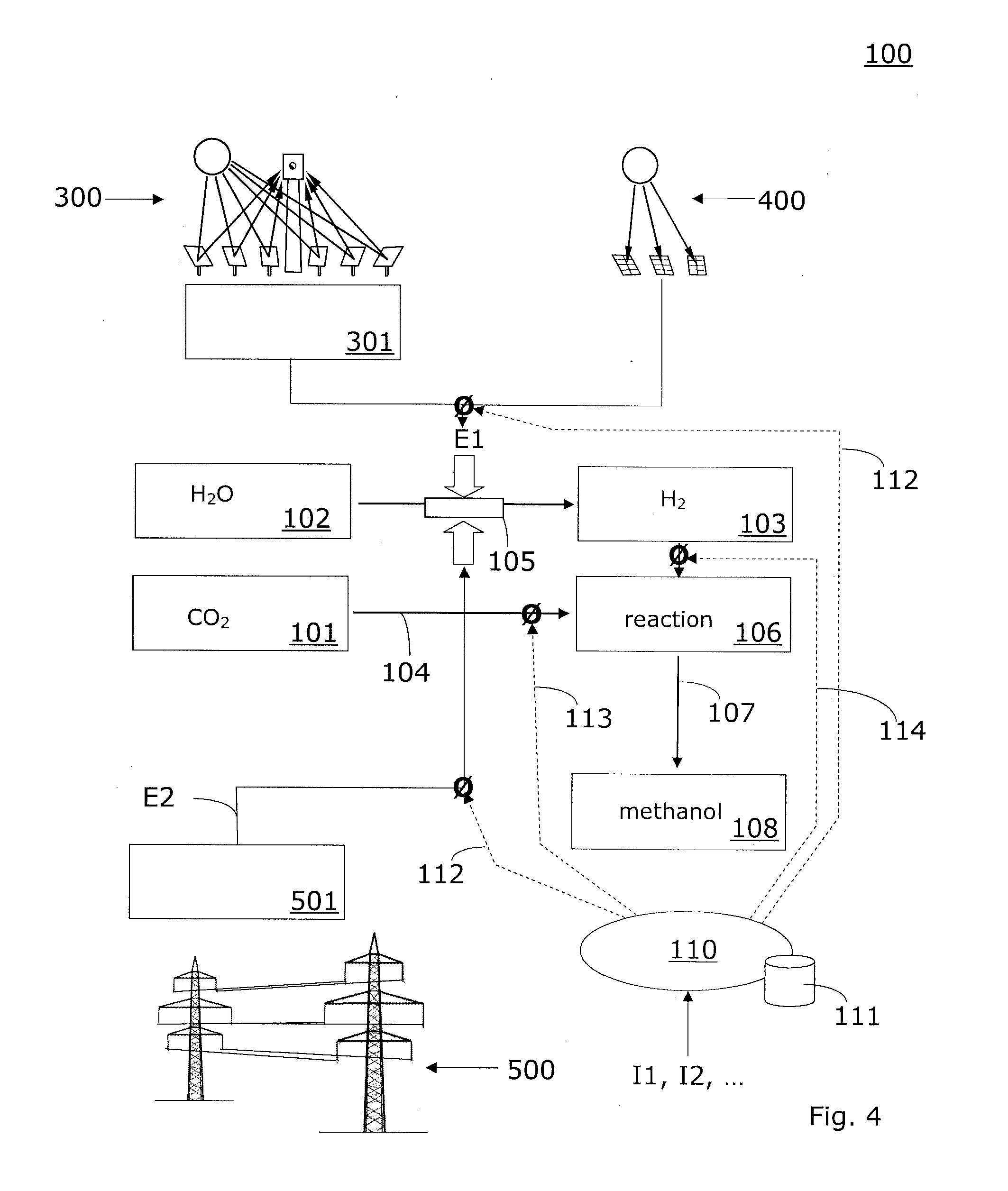
The invention relates to methods and facility systems (100) for providing storable and transportable carbon-based energy carriers (108) by application of carbon dioxide (101) as a carbon supplier and by application of electric energy (E1, E2). The facility system (100) comprises a plant (300, 301; 400) for providing a first portion of energy in the form of direct current energy (E1) from renewable energy sources. In addition, a power supplies facility (501) is provided for tying the facility system (100) to a mixed network (500), wherein the power supplies facility (501) produces a second portion of energy in the form of direct current energy (E2) from an alternating current voltage of the mixed network (500). A device (102, 105) is adapted to provide hydrogen (103), wherein a part of the energy requirement of this device (102, 105) is covered by said first portion of energy and another part is covered by said second portion of energy. A carbon dioxide supply serves for introducing carbon dioxide (101) and a reaction area (106) is provided for producing a hydrocarbon, preferably methanol (108).

Description

CROSS-REFERENCES TO RELATED APPLICATIONS[0001]The present application claims the priorities of Patent Cooperation Treaty Application No. PCT / EP2009 / 060472, filed on Aug. 13, 2009; European Patent Application No. 09154271.2, filed Mar. 4, 2009; and Patent Cooperation Treaty Application No. PCT / EP2008 / 067895, filed Dec. 18, 2008; all of which are incorporated herein by reference in their entirety for all purposes.FIELD OF THE INVENTION[0002]The present application concerns methods and facility systems for providing storable and transportable carbon-based energy carriers by application of carbon dioxide as a carbon supplier and by application of electric energy.BACKGROUND OF THE INVENTION[0003]Carbon dioxide CO2 (often called carbonic acid gas) is a chemical compound composed of carbon and oxygen. Carbonic acid gas is a color- and odorless gas. It is a natural component of the air, with a low concentration, and is produced by in animals during the cell respiration, but also during the ...

Claims


Application Information

Patent Timeline
Patent Type & Authority Applications(United States)
IPC IPC(8): C07C27/00B01J19/08C25B3/25
CPCC25B1/04C25B15/00C10G2/50Y02E70/10C25B3/04Y02E60/366Y02P20/133Y02E60/36Y02E50/10C25B3/25Y02E60/32
Inventor GRAUER, PETERMEYER-PITTROFF, ROLAND
Owner SILICON FIRE AG
Learn More