Membrane pump head for a homogenizer or a high-pressure pump

a technology of high-pressure pumps and membrane pumps, which is applied in the direction of applications, flexible wall reciprocating engines, mechanical equipment, etc., can solve the problems of major product losses, unacceptable service life of seals, and forged pump blocks which are extremely expensive to manufacture, and achieves the effect of simple manufacturing and more economical

Inactive Publication Date: 2012-01-19
TETRA LAVAL HLDG & FINANCE SA
View PDF6 Cites 27 Cited by
  • Summary
  • Abstract
  • Description
  • Claims
  • Application Information

AI Technical Summary

Benefits of technology

[0011]One object of the present invention is to realise a membrane pump head for a homogenizer which enjoys all of the advantages of the membrane pump, without the pump blocks becoming too large in size.
[0012]A further object of the present invention is that the pump blocks will become considerably simpler to manufacture and thereby considerably more economical.

Problems solved by technology

Since, in food contexts, it is not possible to lubricate the seal, for example by permitting a portion of the product to leak past, the service life of the seals becomes unacceptably short.
In addition to the hygienic drawbacks, this would give major product losses.
This also is a contributory factor in their short service life.
Today's piston pumps which are employed in homogenizers moreover display forged pump blocks which are extremely expensive to manufacture.
Membrane pump heads cannot normally be applied on a homogenizer, since the diameter of the membrane must be extremely large in order to correspond with the stroke volume of the existing piston, with the result that a piston pump with membrane pump heads requires a considerably greater centre distance between the pistons than does a conventional piston machine.
In this embodiment, the pump blocks will be considerably larger and more expensive if there is to be room for membranes of the diameter required by the stroke volume of the piston.
Similarly, this embodiment causes a relatively unfavourable pressurization of the membranes and relatively large flow losses.

Method used


Image

  • Membrane pump head for a homogenizer or a high-pressure pump
  • Membrane pump head for a homogenizer or a high-pressure pump
  • Membrane pump head for a homogenizer or a high-pressure pump

Examples


Embodiment Construction

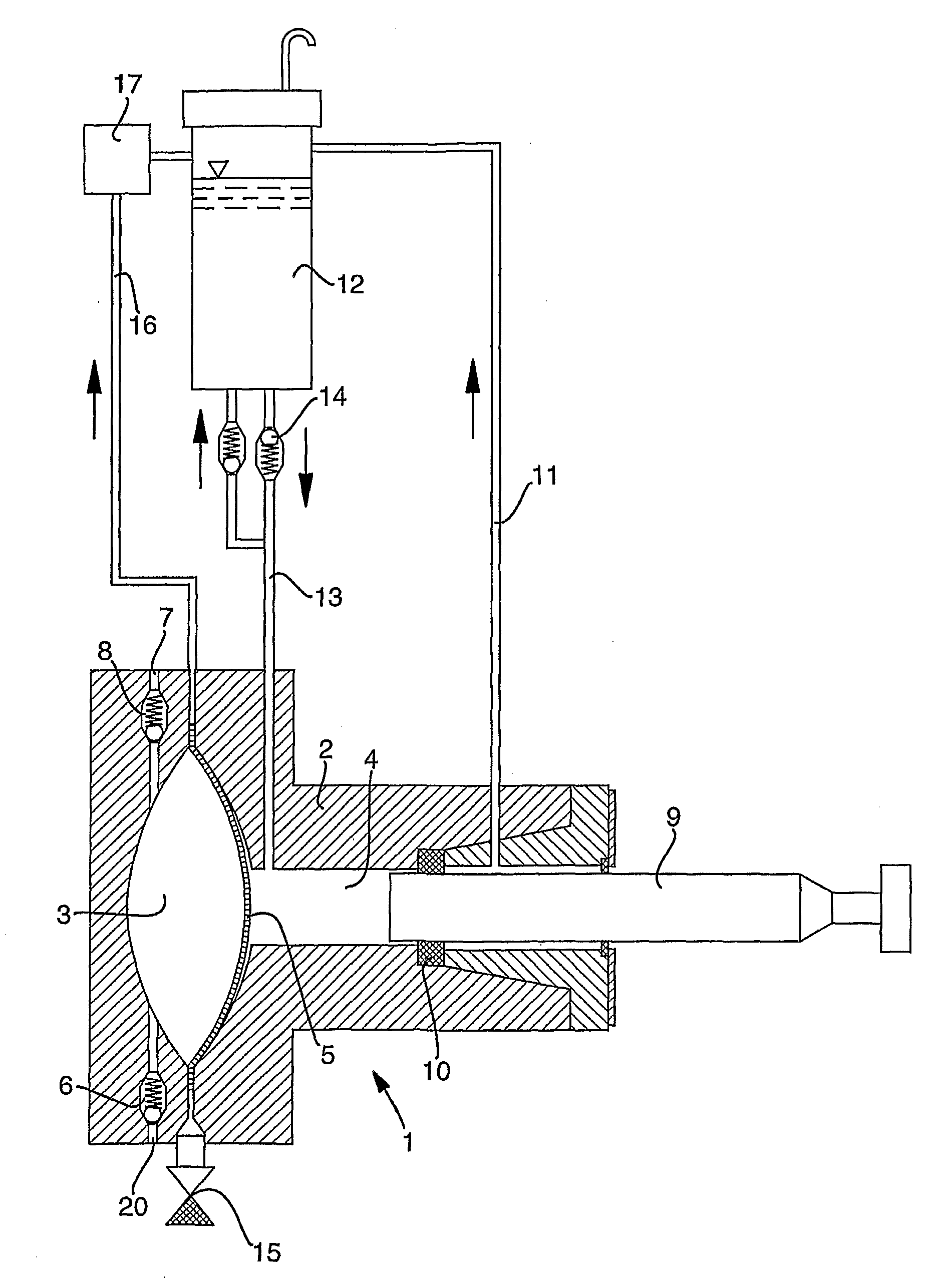
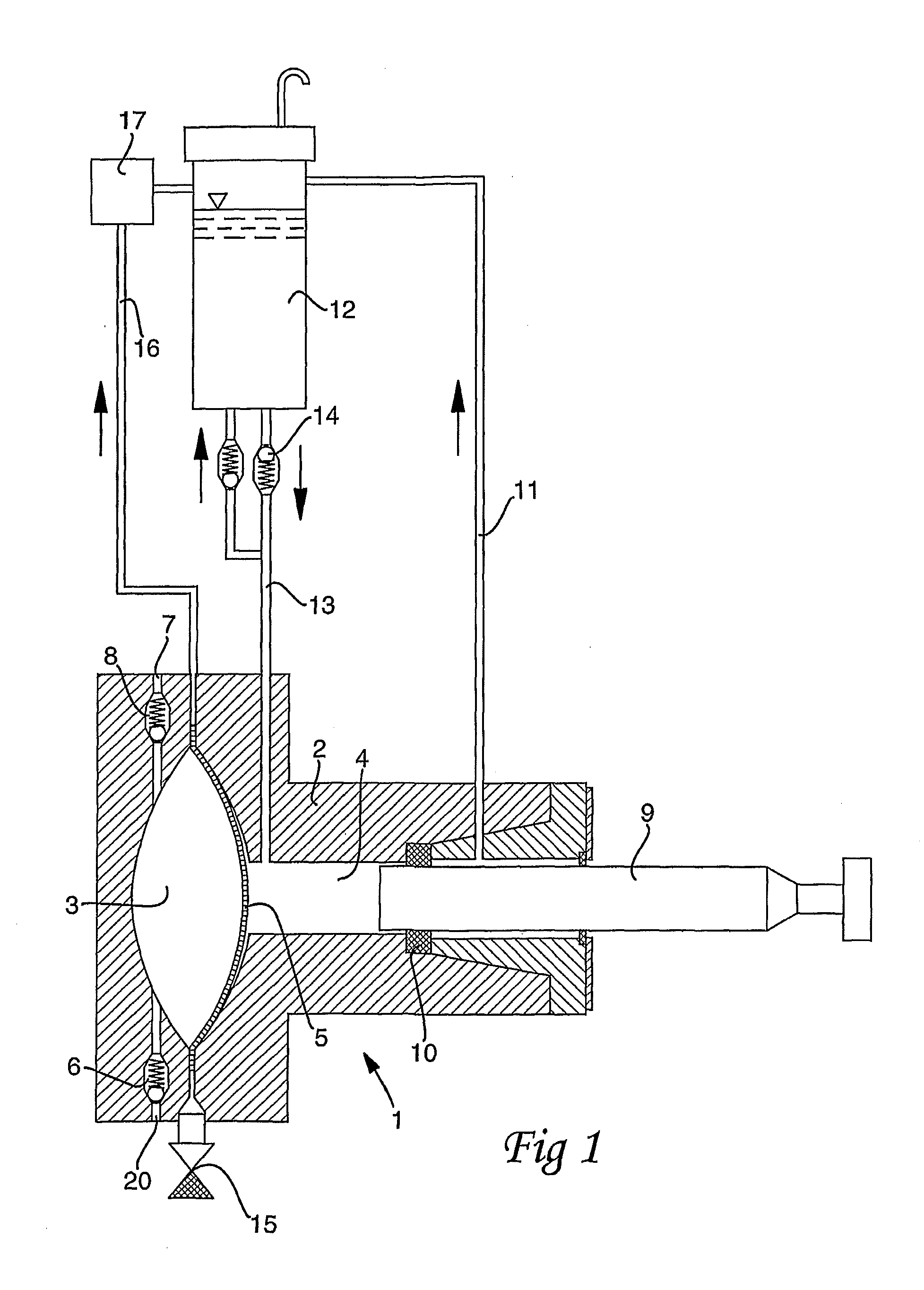
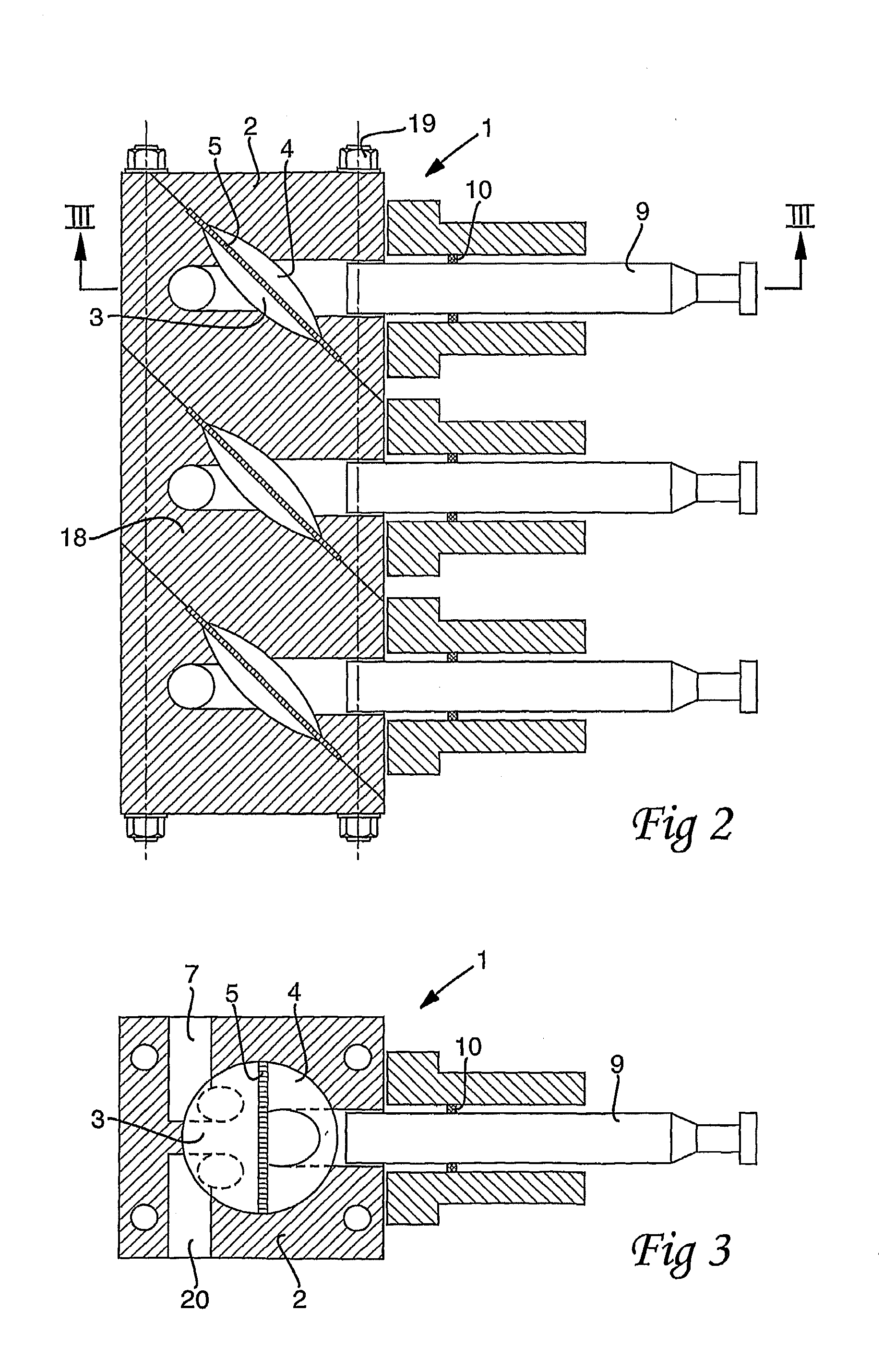
[0023]FIG. 1 shows a membrane pump head 1, as it may appear in principle. The membrane pump head 1 comprises a pump housing 2 which encloses a product chamber 3 and a hydraulic chamber 4. The product chamber 3 and the hydraulic chamber 4 are separated by means of a membrane 5.

[0024]The product chamber 3 is connected to a product inlet 20. The product inlet 20 is provided with a valve 6. The product chamber 3 is also connected to a product outlet 7. The product outlet 7 is provided with a valve 8.

[0025]A piston 9 acts in the hydraulic chamber 4, which is filled with a hydraulic fluid, preferably oil. The piston 9 is sealed against the pump housing 2 by means of a seal 10. The seal 10 is of a type which withstands high pressure and it is lubricated constantly by the hydraulic fluid. The excess flow of hydraulic fluid is led via the conduit 11 to a hydraulic fluid container 12 which, when necessary, replenishes hydraulic fluid in the hydraulic chamber 4 through the conduit 13 and the n...


PUM


Abstract

The disclosure relates to a membrane pump head for a homogenizer or a high-pressure pump. The membrane pump head comprises at least one pump head enclosed in a pump housing. The membrane pump head also includes a product chamber with inlet and outlet for the product, as well as a hydraulic chamber in which a piston is disposed to operate. The product chamber and the hydraulic chamber are separated by a double membrane. The membrane is oriented at 15-75° in relation to the longitudinal direction of the piston.

Description

TECHNICAL FIELD[0001]The present invention relates to a membrane pump head for a homogenizer or a high-pressure pump, comprising at least one pump head enclosed in a pump housing, the membrane pump head further including a product chamber with inlet and outlet for the product, and a hydraulic chamber in which a piston is disposed to operate, the product chamber and the hydraulic chamber being separated by a double membrane.BACKGROUND ART[0002]Homogenization is an industrial process which has been in use for a considerable time and whose purpose is, in, for example, a fat emulsion such as milk, to split the largest fat globules into smaller fat globules and by such means stabilize the fat emulsion. For, for example milk, this implies that the setting of cream is prevented, and the greater proportion of all consumer milk today is homogenized.[0003]Homogenization normally takes place by mechanical processing, so that the fat emulsion which is at a high input pressure is forced at high ...

Claims


Application Information

Patent Timeline
Patent Type & Authority Applications(United States)
IPC IPC(8): F04B43/02
CPCF04B43/107F04B43/067A01J11/16F04B43/0054F04B43/009
Inventor JOHANSSON, CLAES-GORANWENDESTAM, NILS
Owner TETRA LAVAL HLDG & FINANCE SA
Why Eureka
Try Eureka