Ignition apparatus, internal-combustion engine, ignition plug, plasma equipment, exhaust gas degradation apparatus, ozone generating/sterilizing/disinfecting apparatus, and odor eliminating apparatus

a technology for odor elimination and combustion apparatus, which is applied in the direction of combustion air/fuel air treatment, energy-based chemical/physical/physicochemical processes, and domestic cooking appliances. it can solve problems such as output degradation, ignition apparatus using the above-mentioned microwave corona discharge can be hardly put to practical use, and the stability of combustion/reaction is impaired. it achieves the effect of improving combustion speed, stabilizing ignition, and improving odor elimination

Active Publication Date: 2012-01-19
I LAB INC
View PDF5 Cites 0 Cited by
  • Summary
  • Abstract
  • Description
  • Claims
  • Application Information

AI Technical Summary

Benefits of technology

[0028]The present invention is therefore contrived in view of the above-mentioned problems, and its object is to provide an ignition apparatus capable of achieving improvement of output, exhaust gas cleaning, and improvement of fuel consumption rate by performing the stable and highly efficient combustion / reaction even when the fuel ratio of the mixture is decreased and the combustion / reaction of the lean mixture is performed in a heat engine such as a reciprocating engine, a rotary engine, a jet engine and a gas turbine, or a plasma equipment.
[0118]It is possible to provide the ozone generating / sterilizing / disinfecting apparatus and the odor eliminating apparatus easily generating a great amount of O3 at a low cost, in a high-efficiently and energy saving manner.

Problems solved by technology

However, when the fuel ratio of the mixture of a conventional internal-combustion engine and the like is decreased, stability of combustion / reaction is impaired, for example, its cycle fluctuates.
As a result, problems such as output degradation occur.
The ignition apparatus using the above-mentioned microwave corona discharge can be hardly put to practical use, since fuel consumption rate improvement and stability of the combustion / reaction cannot be expected comparing with an ignition method using the conventional spark discharge.
In addition, in the gasoline internal-combustion engine using the above-mentioned high frequency electric field generator, the magnetron is directly mounted on the engine, so that there is occurrence of various troubles in terms of durability, vibration resistance, limitations of mounting space, ambient temperature (that is, temperature of an engine increases), and malfunction prevention of a control system due to microwave leakage.
For this reason, the gasoline internal-combustion engine of this kind can be hardly put to practical use.

Method used


Image

  • Ignition apparatus, internal-combustion engine, ignition plug, plasma equipment, exhaust gas degradation apparatus, ozone generating/sterilizing/disinfecting apparatus, and odor eliminating apparatus
  • Ignition apparatus, internal-combustion engine, ignition plug, plasma equipment, exhaust gas degradation apparatus, ozone generating/sterilizing/disinfecting apparatus, and odor eliminating apparatus
  • Ignition apparatus, internal-combustion engine, ignition plug, plasma equipment, exhaust gas degradation apparatus, ozone generating/sterilizing/disinfecting apparatus, and odor eliminating apparatus

Examples


first embodiment

[0159][First Embodiment of Ignition Apparatus]

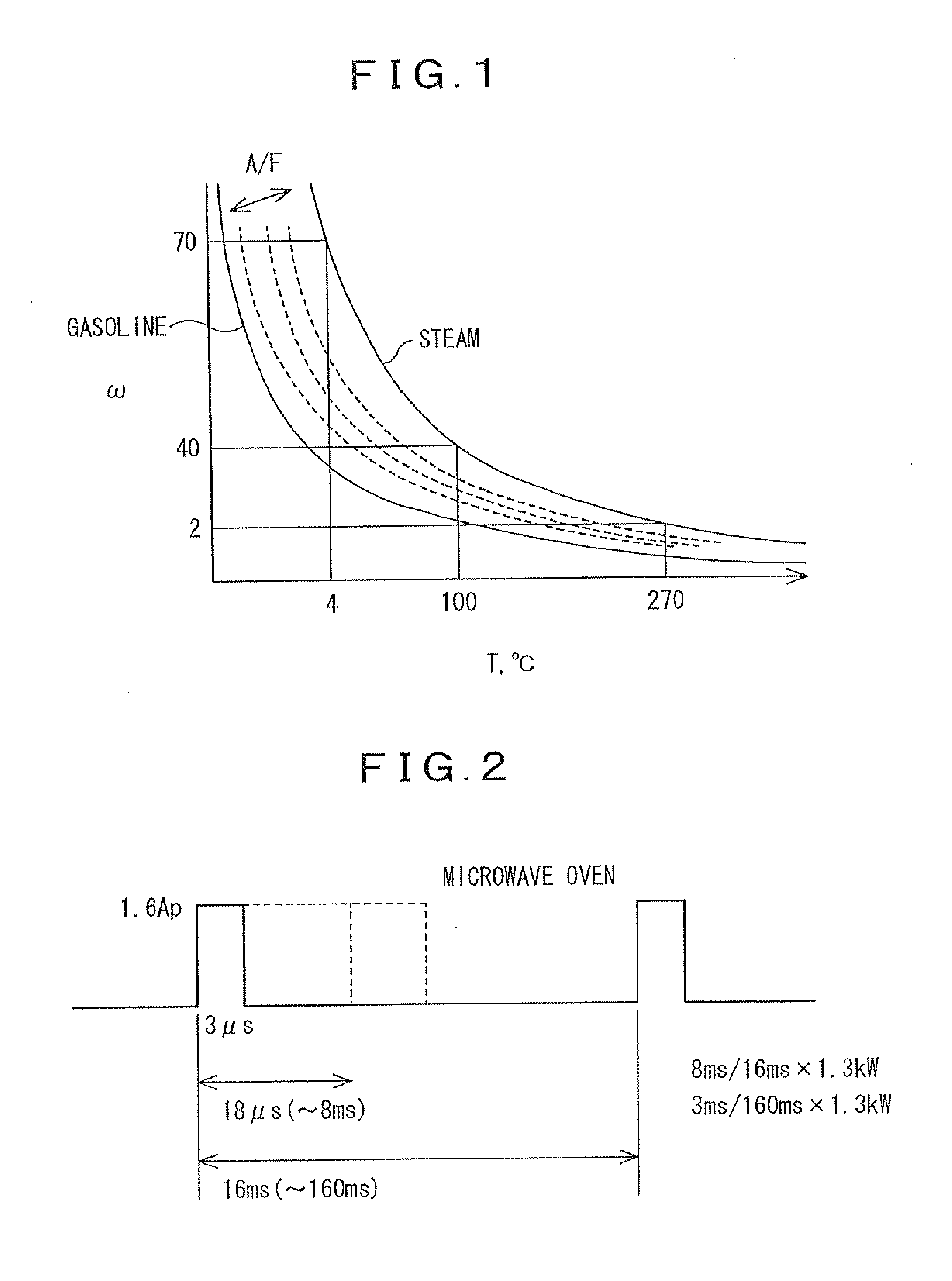
[0160]In a heat engine or a plasma equipment, mixture of reactive gas and oxidation gas is provided. In a combustion / reaction field in which a combustion / reaction of the mixture is caused, for example, a combustion / reaction chamber of an engine, when temperature of the mixture is increased or ignition is carried out by microwave, it is necessary to efficiently transmit required energy to the combustion / reaction chamber for the purpose of the temperature increase or the ignition. For this reason, it is preferable that resonance frequency determined by the shape of the combustion / reaction chamber, dielectric constant (ε) of the mixture and the like corresponds to frequency of the microwave. On the other hand, as a magnetron used for generating the microwave, a number of the magnetrons which have a oscillating frequency of 2.45 GHz and allow water molecules to resonate are already manufactured and used for home electric appliances. In addit...

second embodiment

[0181][Second Embodiment of Ignition Apparatus]

[0182]The ignition apparatus according to the second embodiment includes the microwave radiation means and the ignition means in the same manner as the ignition apparatus according to the above-mentioned first embodiment. Further, the ignition apparatus includes control means for controlling the microwave radiation means and the ignition means.

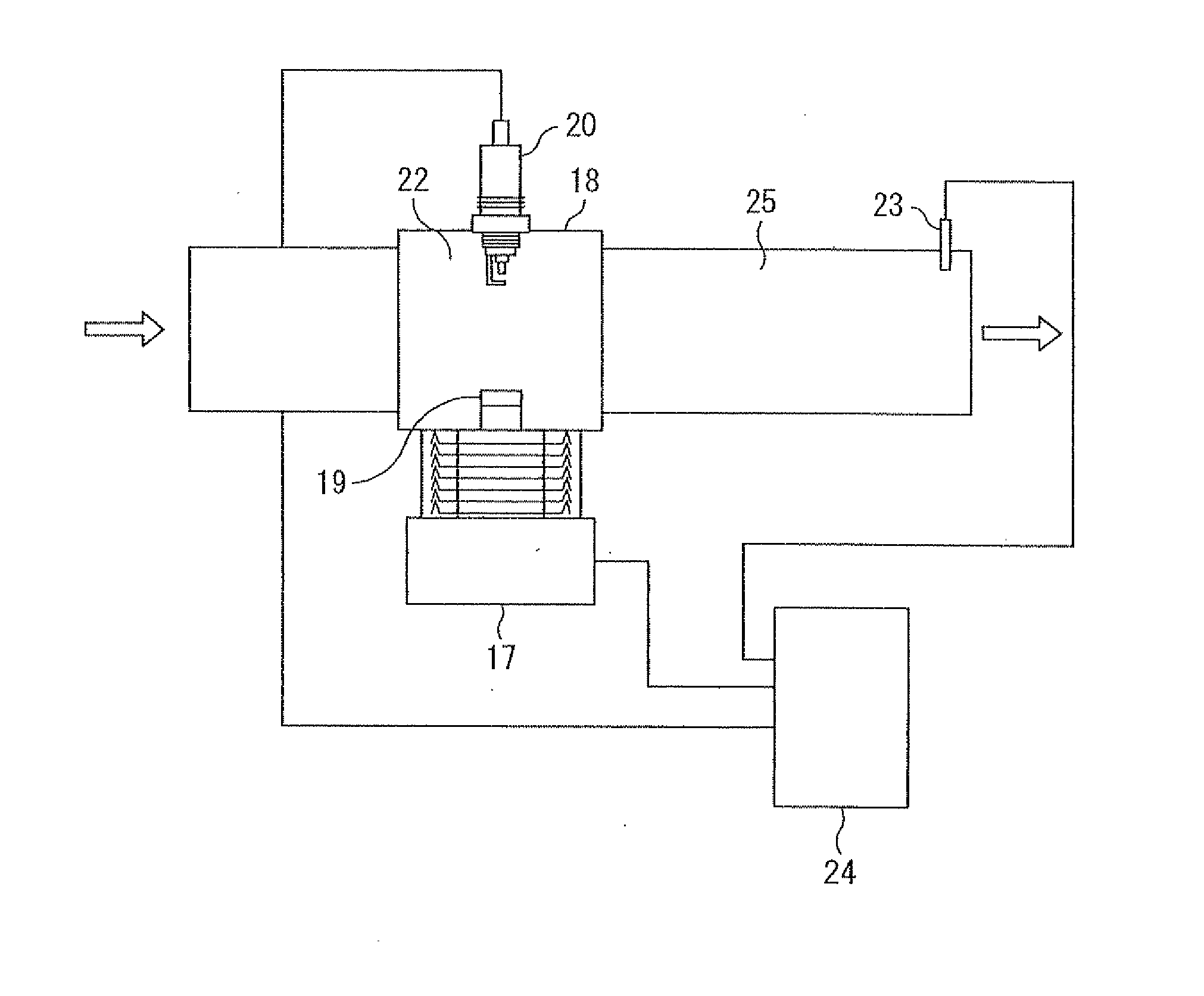
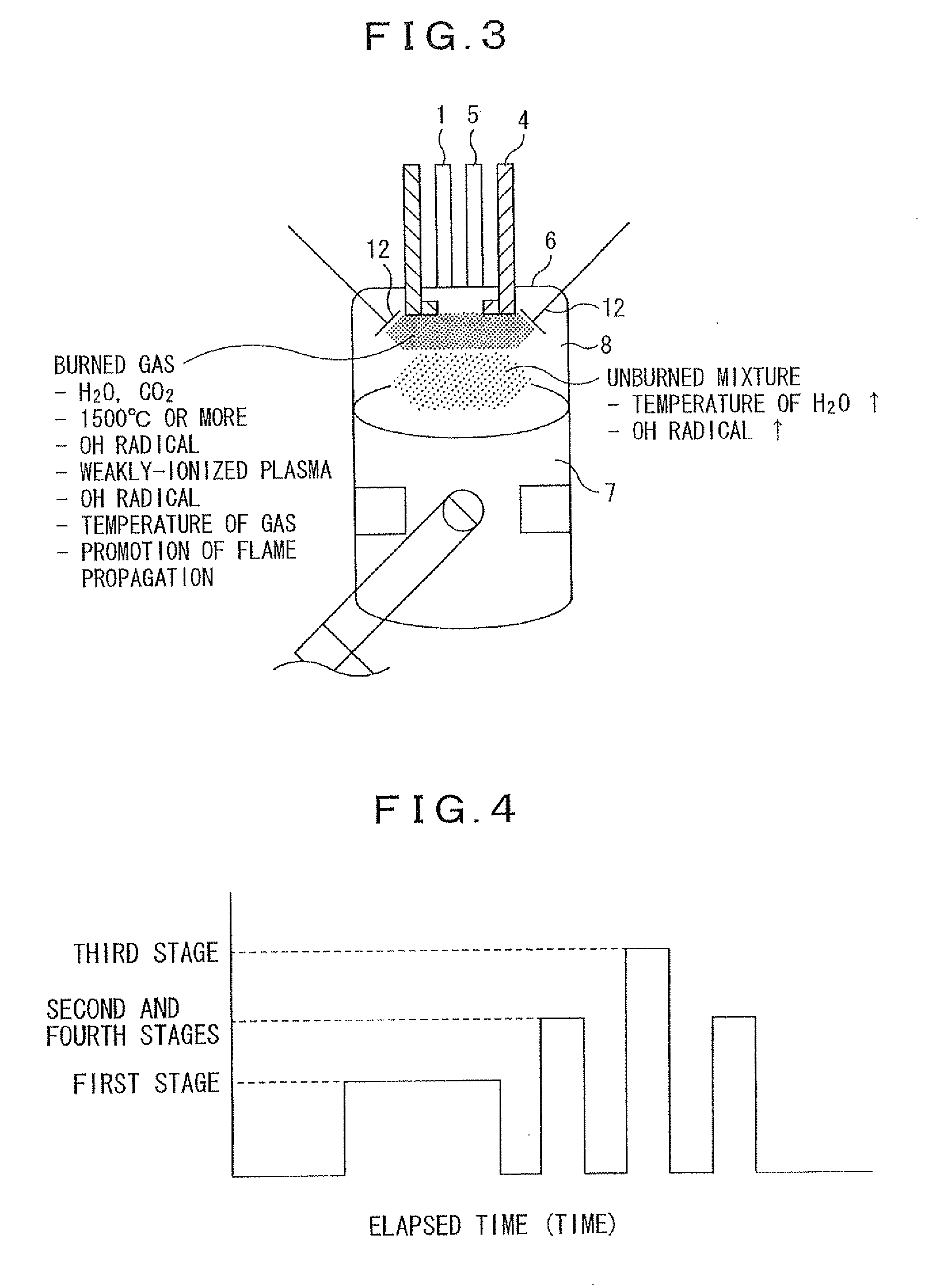
[0183]The control means controls the microwave radiation means and the ignition means and performs following cycle repeatedly. The cycle comprises increasing the temperature of the mixture in the combustion / reaction chamber 8 or generating radicals by radiating the microwave into a combustion / reaction chamber 8 by the microwave radiation means as shown in FIG. 3, then performing the ignition to the mixture by the ignition means, next promoting the combustion / reaction of the mixture in the combustion / reaction chamber by radiating the microwave into the combustion / reaction chamber by the microwave r...

third embodiment

[0214][Third Embodiment of Plasma Equipment]

[0215]As shown in FIG. 13, the plasma equipment according to the present invention makes smaller and less expensive microwave radiation means 19 according to the first embodiment or the second embodiment of the present invention. This is realized by fitting the antenna 19 to the conventional spark plugs or the glow plugs. In this case, an end of the antenna 19 is branched so as to surround the ignition / discharge unit, thereby forming a strong electrical field.


PUM


Abstract

Stable and highly efficient combustion / reaction is provided, even when fuel ratio of mixture is decreased and combustion / reaction of the lean mixture is performed in a heat engine such as a reciprocating engine, for controlling dielectric constant of mixture in a combustion / reaction chamber 8 by introducing water and / or exhaust gas into the combustion / reaction chamber, by introducing water and / or exhaust gas into the combustion / reaction chamber. A microwave radiation antenna for irradiation of the combustion / reaction chamber, and a discharge unit for igniting the mixture in the combustion / reaction chamber are provided. The dielectric constant of the mixture before the combustion / reaction of the mixture is controlled so that the resonance frequency of the mixture corresponds to the frequency of the microwave.

Description

CROSS-REFERENCE TO RELATED APPLICATIONS[0001]This application is a Divisional Application of 12 / 083,608, filed on Apr. 15, 2008 which is a National Phase Application (35 USC 371) of PCT / JP2006 / 319850, filed on Oct. 4, 2006 and claims priority under 35 USC 119 of Japanese Application No. 2006-255109, filed Sep. 20, 2006.[0002]The teachings of Japanese Application No. 2006-255109, filed Sep. 20, 2006 are incorporated herein in their entirety, inclusive of the specification, claims and drawings.FIELD OF ART[0003]The present invention relates to an ignition apparatus used in a heat engine such as a reciprocating engine, a rotary engine, a jet engine and a gas turbine, or a plasma equipment.[0004]The present invention relates to an internal-combustion engine to which the ignition apparatus according to the present invention is suitably applied.[0005]The present invention relates to an ignition plug that is suitably applied to the ignition apparatus according to the present invention.[000...

Claims


Application Information

Patent Timeline
Patent Type & Authority Applications(United States)
IPC IPC(8): H05H1/50
CPCB01D53/32Y02T10/121C01B13/10F02B23/08F02B47/02F02B47/08F02M27/04F02P23/045H05B6/681H05B6/806H05B2206/045Y02B40/143Y02T10/125A61L2/202F02M25/03B01D2259/818Y02B40/00Y02T10/12F02P15/02F02P3/0407F02P5/00F02P9/007F02P15/10F02P23/04B01J19/08
Inventor IKEDA, YUJI
Owner I LAB INC
Why Eureka
Try Eureka