Continuous wave or ultrafast lasers

a laser and ultra-fast technology, applied in wave amplification devices, laser details, electrical equipment, etc., can solve the problems of poor performance of conventional short-pulse mode-locking or q-switching systems, pulse energy is even more severely limited, and the performance of conventional systems has been found to be severely limited. , to achieve the effect of long interaction length of fibers, poor performance and small cross section area

Active Publication Date: 2012-01-19
MASSACHUSETTS INST OF TECH
View PDF7 Cites 20 Cited by
  • Summary
  • Abstract
  • Description
  • Claims
  • Application Information

AI Technical Summary

Benefits of technology

[0006]It has been observed that the poor performance of conventional short-pulse mode-locking or Q-switching systems is mainly due to small cross section area and long interaction length of the fibers used. In fiber lasers, the pulse energy is limited to about one milli-Joule, with a few

Problems solved by technology

It has been observed that the poor performance of conventional short-pulse mode-locking or Q-switching systems is mainly due to small cross section area and long interaction length of the fibers used.
In semiconductor lasers, the

Method used


Image

  • Continuous wave or ultrafast lasers
  • Continuous wave or ultrafast lasers
  • Continuous wave or ultrafast lasers

Examples


Embodiment Construction

[0013]This invention is not limited in its application to the details of construction and the arrangement of components set forth in the following description or illustrated in the drawings. The invention is capable of other embodiments and of being practiced or of being carried out in various ways. Also, the phraseology and terminology used herein is for the purpose of description and should not be regarded as limiting. The use of “including,”“comprising,”“having,”“containing,”“involving,” and variations thereof herein is meant to encompass the items listed thereafter and equivalents thereof as well as additional items.

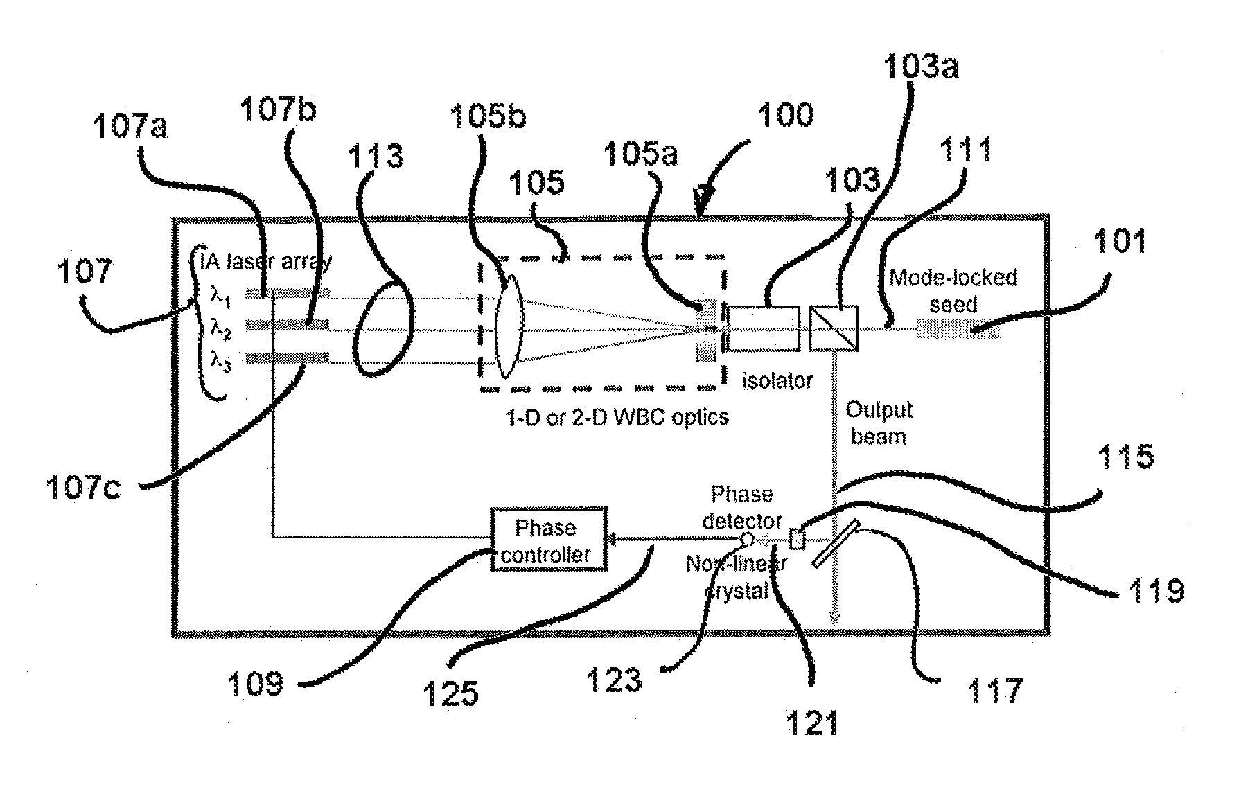
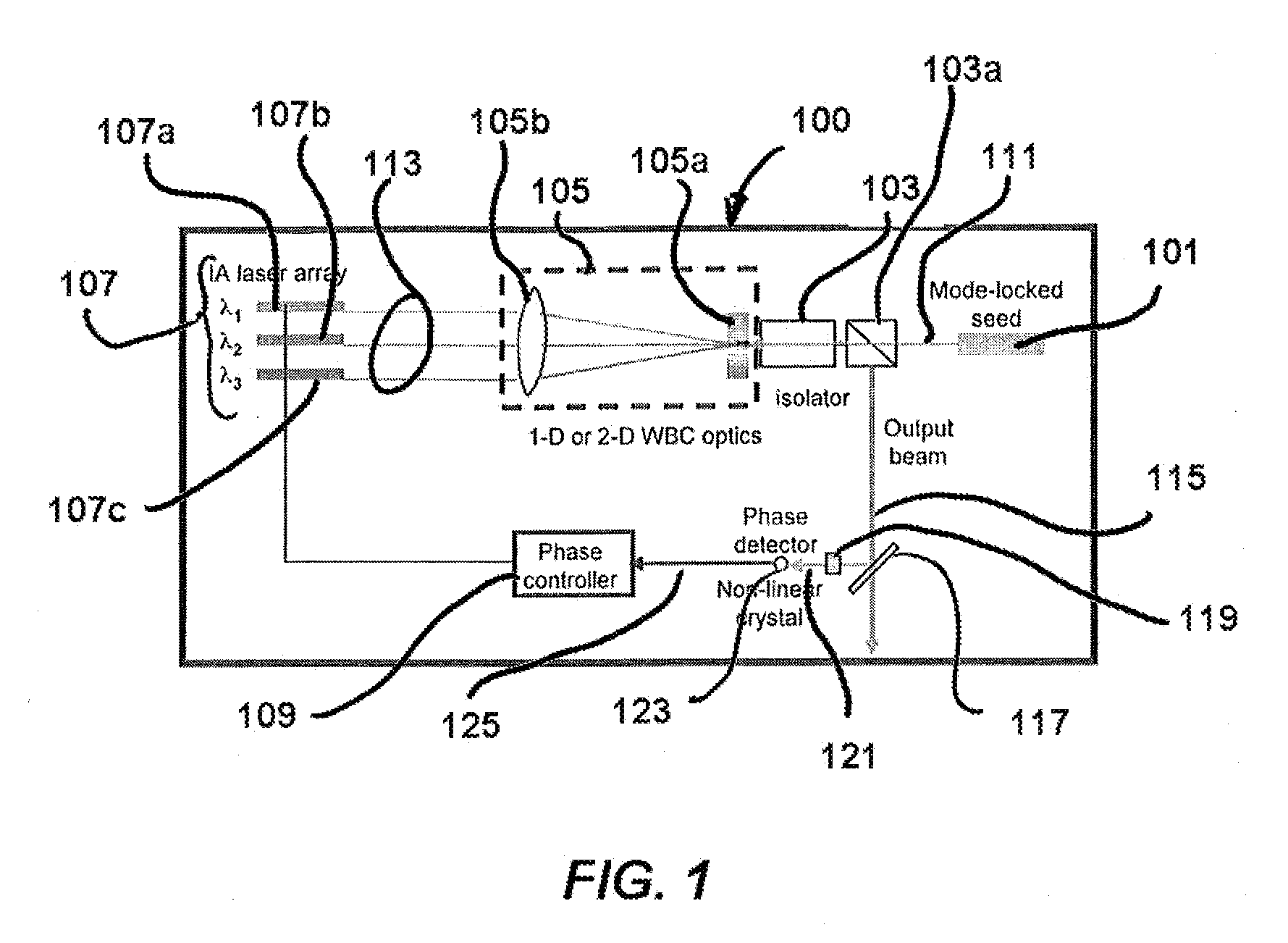
[0014]FIG. 1 is a schematic block diagram showing a basic folded architecture for generating high power CW or ultrafast lasers according to aspects of embodiments of the invention. Systems according to the illustrated basic architecture, 100, include a mode-locked master oscillator, 101; a Faraday isolator, 103, including an input polarizer which separates and redire...


PUM


Abstract

A laser system comprises: a seed oscillator, having a seed output; dispersive optics, operative to receive the seed output and divide the seed output into spectrally separate seed components; an array of individually addressable, phase adjustable laser amplifiers corresponding to the spectrally separate components, each laser amplifier receiving as its seed one of the spectrally separate seed components and producing one of the spectrally separate amplified components; and phase actuators controlling the individually addressable, phase adjustable laser amplifiers. A method of operating a laser system comprises: generating a seed signal; dividing the seed signal into spectrally separate component signals; amplifying the spectrally separate component signals; recombining the spectrally separate component signals into an amplified output; and controlling phases of the amplified spectrally separate component signals. Both single-pass and double-pass amplifier array versions are disclosed.

Description

FEDERALLY SPONSORED RESEARCH[0001]This invention was made with Government support under Air Force contract, FA8721-05-C-0002, Program #221. The Government may have certain rights to this invention.BACKGROUND OF INVENTION[0002]1. Field of Invention[0003]The present invention relates to short pulse generation by diode and fiber lasers using mode-locking or Q-switching technologies. In particular, the invention relates to such systems employing plural amplifiers arranged to reduce the effects of non-linearities on gain-bandwidth and power output.[0004]2. Discussion of Related Art[0005]Short pulse generation by diode and fiber lasers employing mode-locking or Q-switching technologies have been an active area of research in the last three decades. The performance of such systems, however, has yet to approach other solid state lasers.SUMMARY OF INVENTION[0006]It has been observed that the poor performance of conventional short-pulse mode-locking or Q-switching systems is mainly due to sma...

Claims


Application Information

Patent Timeline
IPC IPC(8): H01S3/098H01S3/13
CPCH01S3/1307H01S3/2308H01S3/2391H01S3/2383H01S3/2333
Inventor CHANN, BIENRIPIN, DANIEL J.FAN, TSO YEESANCHEZ-RUBIO, ANTONIO
Owner MASSACHUSETTS INST OF TECH
Why Eureka
Try Eureka