Cleaving method for a glass film, manufacturing method for a glass roll, and cleaving apparatus for a glass film

a technology of glass film and cleaving apparatus, which is applied in the direction of glass forming apparatus, glass tempering apparatus, glass reforming apparatus, etc., can solve the problems of difficult thermal stress to efficiently act on glass film and more conspicuous problems, and achieve the effect of efficient cleaving of glass film

Active Publication Date: 2012-01-26
NIPPON ELECTRIC GLASS CO LTD
View PDF36 Cites 98 Cited by
  • Summary
  • Abstract
  • Description
  • Claims
  • Application Information

AI Technical Summary

Benefits of technology

[0037]As described above, according to the present invention, it is possible to efficiently cleave a glass film by a thermal stress without causing any cleaving failure even when a glass sheet to be cleaved is thin as a glass film.

Problems solved by technology

Thus, it is difficult for the thermal stress to act on the glass film efficiently.
In particular, such a problem becomes more conspicuous as the glass film becomes thinner.

Method used


Image

  • Cleaving method for a glass film, manufacturing method for a glass roll, and cleaving apparatus for a glass film
  • Cleaving method for a glass film, manufacturing method for a glass roll, and cleaving apparatus for a glass film
  • Cleaving method for a glass film, manufacturing method for a glass roll, and cleaving apparatus for a glass film

Examples


first embodiment

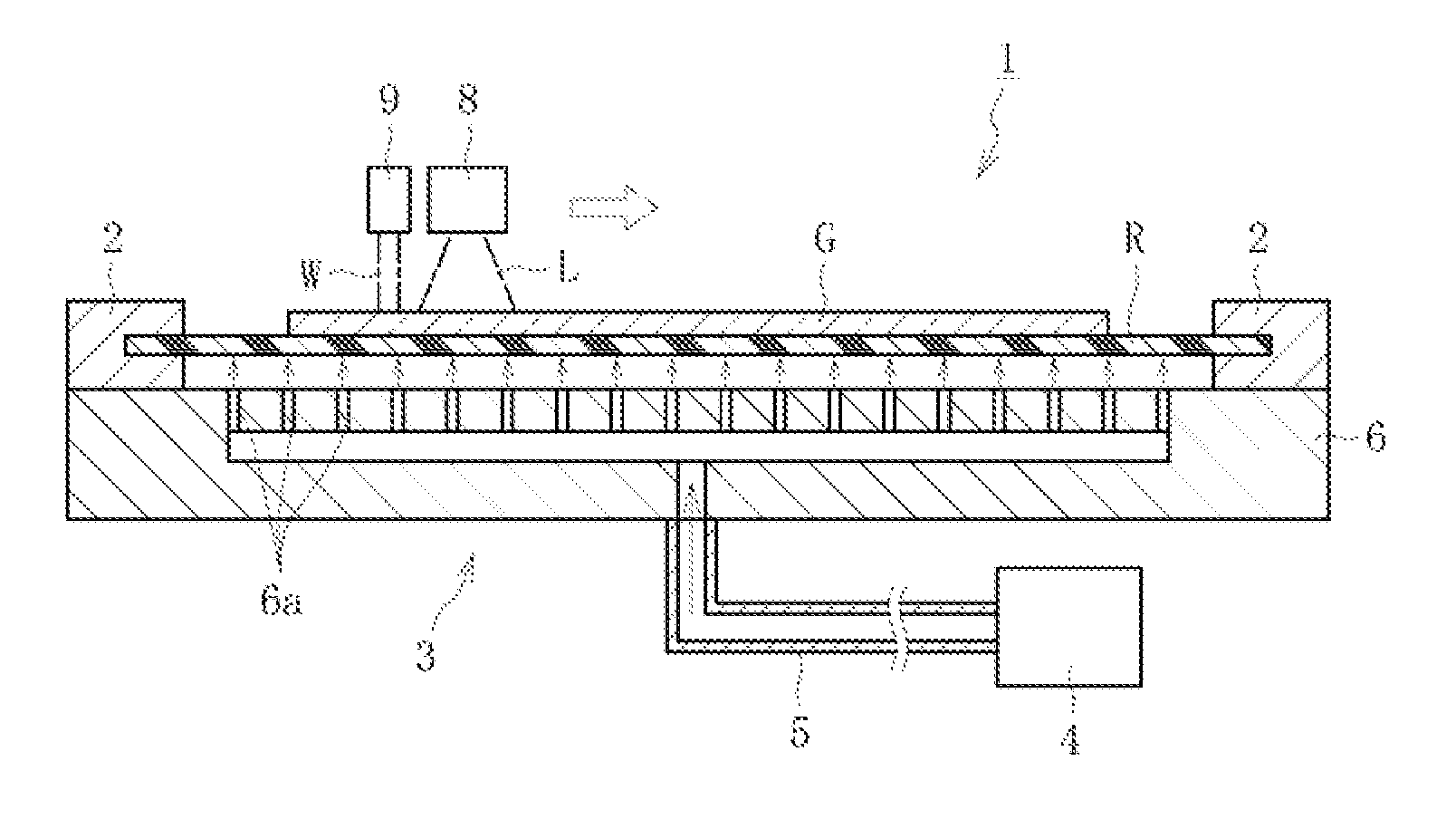
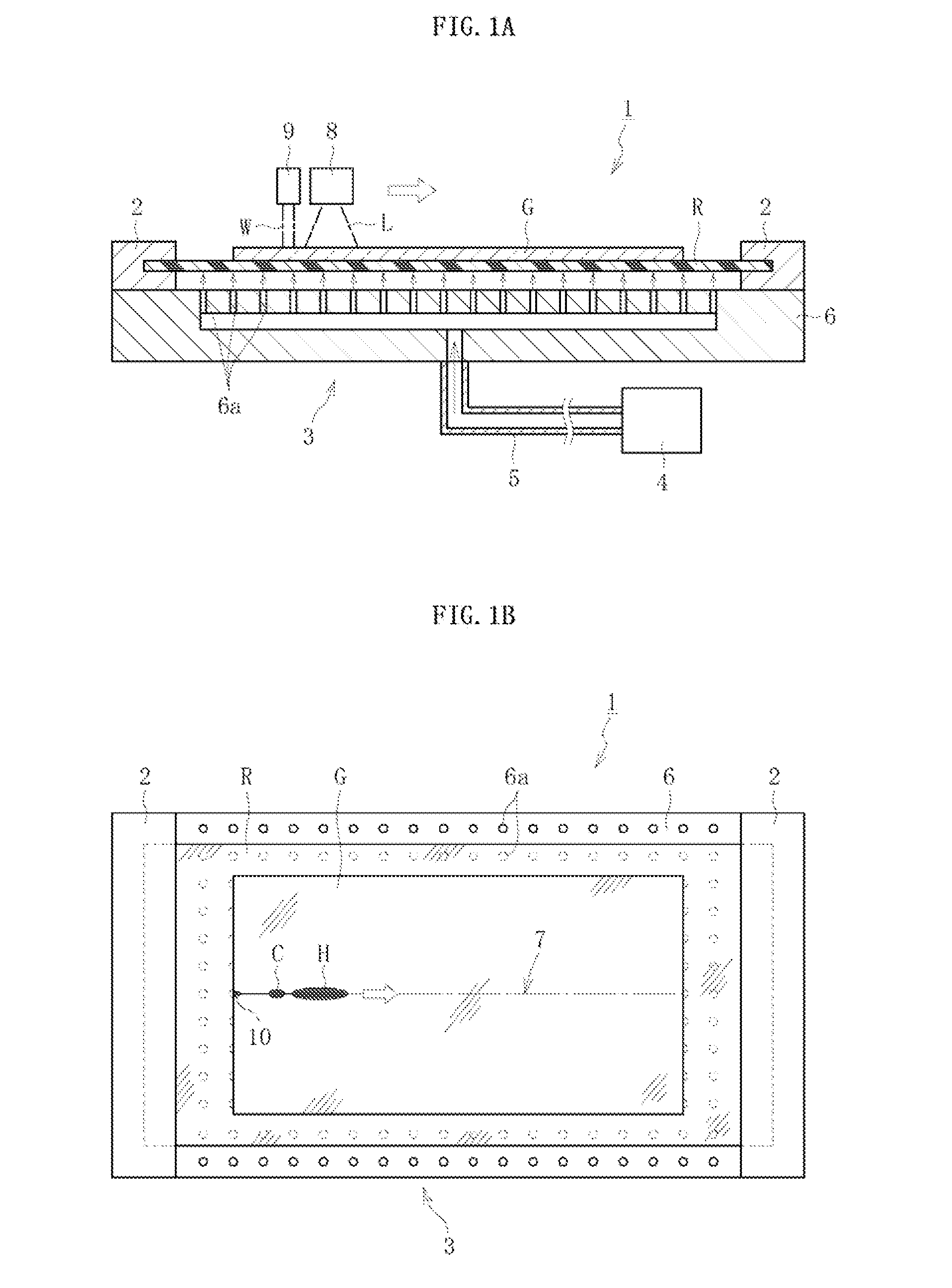
[0049]FIGS. 1A and 1B are views illustrating a practical situation of a cleaving apparatus for a glass film and a cleaving method for a glass film according to a first embodiment of the present invention. A cleaving apparatus 1 according to the present invention includes a resin sheet R for supporting a glass film G from below, gripping means 2 for gripping two sides of the resin sheet R opposing in a direction orthogonal to a width direction of the resin sheet R, and floating means 3 for floating the resin sheet R gripped by the gripping means 2 by blowing a gas on the resin sheet R from below. Note that, the gripping means 2 may grip all the four sides of the resin sheet R.

[0050]As illustrated in FIG. 1A, the floating means 3 includes a gas supply source 4, and a floating stage 6 connected to the gas supply source 4 through piping 5. In a top surface of the floating stage 6, a plurality of gas jet holes 6a are provided, and a gas supplied from the gas supply source 4 through the p...

second embodiment

[0058]FIGS. 3A and 3B are views illustrating a practical situation of a cleaving apparatus for a glass film and a cleaving method for a glass film according to the present invention. The second embodiment is different from the first embodiment in that a cleaving step is executed while conveying an elongated glass film G.

[0059]Specifically, in a cleaving apparatus 1 according to the second embodiment, a glass roll 13 obtained by rolling the elongated glass film G around a roll core 13a is arranged on an upstream side, and the glass film G unrolled from the glass roll 13 on the upstream side is transported toward a downstream side. Then, on a transport path of the glass film G unrolled from the glass roll 13 on the upstream side, there are arranged a first conveyor 14, a floating stage 6, and a second conveyor 15 in the stated order from the upstream side.

[0060]The first conveyor 14 and the second conveyor 15 have the same structure, and as illustrated in FIG. 3B, respective conveyor ...

third embodiment

[0063]FIG. 4 is a view illustrating a practical situation of a cleaving apparatus for a glass film and a cleaving method for a glass film according to the present invention. The third embodiment is different from the second embodiment in that a cleaving step is directly executed for a glass film G drawn out of a forming device 21 for forming the glass film G.

[0064]Specifically, the forming device 21 carries out an overflow downdraw method, and includes, in the following order from above, a forming zone 21A having a forming member 21x inside a forming furnace, an annealing zone 21B having annealing means (annealer), and a cooling zone 21C having cooling means. The glass film G drawn downward from the cooling zone 21C of the forming device 21 is conveyed in a lateral direction while being smoothly curved by conversion rollers 22, and is then placed on a resin sheet R suspended between a first conveyor 14 and a second conveyor 15 so that the glass film G is transported toward a downstr...


PUM

PropertyMeasurementUnit
thicknessaaaaaaaaaa
thicknessaaaaaaaaaa
thermal stressaaaaaaaaaa

Abstract

In a cleaving apparatus (1) for a glass film, an initial crack (10), which is formed at a leading end portion of a preset cleaving line (7) of a glass film (G), is propagated along the preset cleaving line (7) by a thermal stress generated in the glass film (G) through localized heating performed along the preset cleaving line (7) and cooling of a heated region resulting from the localized heating. At this time, a resin sheet (R) having higher flexibility than the glass film (G) is arranged in a cleaving region, and the resin sheet (R) is floated by blowing a gas on a lower surface of the resin sheet (R) by a floating unit (3). Then, a preset cleaving portion of the glass film (G) including the preset cleaving line (7) is lifted and supported while being covered with the floated resin sheet (R) from below, and in this state, the glass film (G) is cleaved.

Description

TECHNICAL FIELD[0001]The present invention relates to an improvement of a technology for cleaving a glass film by a thermal stress generated along with localized heating performed along a preset cleaving line of the glass film and cooling of a heated region resulting from the localized heating.BACKGROUND ART[0002]As is well known, flat panel displays (FPDs) have become mainstream as image display devices in recent years, the FPDs being typified by a liquid crystal display, a plasma display, a field emission display, an OLED display, and the like. Progress is being made toward reducing the weight of those FPDs, and hence glass substrates used for the FPDs are also currently becoming thinner (being formed as a glass film).[0003]Further, there is a growing use of an organic light-emitting diode as a plane light source, such as a light source for interior illumination, which emits only monochrome (for example, white) light, unlike a display that uses TFTs to blink light of three fine pr...

Claims


Application Information

Patent Timeline
Patent Type & Authority Applications(United States)
IPC IPC(8): C03B21/00C03B35/00C03B23/023B23K26/38B28D5/00C03B33/09
CPCB28D5/0011B65G2249/04B65H2801/61C03B35/246C03B33/074C03B33/091C03B33/0235B32B17/10B23K26/38C03B33/033Y02P40/57
Inventor TERANISHI, YASUOMATSUMOTO, YASUHIROMINARI, TAIKIFURUTA, TAKAYA
Owner NIPPON ELECTRIC GLASS CO LTD
Why Eureka
Try Eureka