Combustion apparatus with improved thermal efficiency

a combustion apparatus and thermal efficiency technology, applied in the direction of lighting and heating apparatus, solid fuel combustion, combustion types, etc., can solve the problems of easy construction automation of remaining ashes, easy to waste solid fuels, and low thermal efficiency, so as to reduce heat loss, improve thermal efficiency, and reduce temperature

Inactive Publication Date: 2012-01-26
KIM SANG KWON
View PDF25 Cites 11 Cited by
  • Summary
  • Abstract
  • Description
  • Claims
  • Application Information

AI Technical Summary

Benefits of technology

[0009]To solve the above problems of the conventional art, it is an object of the present invention to provide a combustion apparatus that ensures complete combustion of solid fuels loaded inside a combustion chamber and reduces a loss of heat to thus improve a thermal efficiency, as well as that lowers temperature of inner walls of the combustion chamber that is continuously exposed to high temperature combustion gases to thereby enhance durability.
[0023]The present invention provides a combustion apparatus that ensures complete combustion of solid fuels loaded inside a combustion chamber and reduces a loss of heat to thus improve a thermal efficiency, as well as that lowers temperature of inner walls of the combustion chamber that is continuously exposed to high temperature combustion gases to thereby enhance durability.

Problems solved by technology

However, since these conventional combustion apparatuses employ a method of putting and burning a lot of solid fuels into the bottom of the combustion vessel, the solid fuels may be incompletely burnt to thus cause a waste of the solid fuels as well as to lower a thermal efficiency.
In addition, since a lot of ashes are generated at a time, it is not so easy to construct automation of the remaining ashes, and it is cumbersome to take out the left ashes from the bottom of the combustion vessel.
Further, if solid fuels have been completely burnt on the bottom of the combustion vessel, new solid fuels should be put into the bottom of the combustion vessel and then ignited again, to thereby make it to perform a continuous combustion process difficult and make a caloric value uneven.
In addition, these solid fuels have caused a problem of discharging a massive amount of gases or particles such as dust, carbon monoxide, soot, gaseous HCL, SOx, NOx, and dioxin that pollute environment during combustion.
However, the conventional solid fuel combustion apparatus supplies air that is needed to burn solid fuels to only outer portions of the solid fuels that have been loaded in the combustion chamber.
Accordingly, the outer portions of the solid fuels are well burnt but the inner portions thereof may be difficult to contact the air necessary for combustion and thus may be burnt imperfectly.
In addition, the inner wall of the combustion chamber is persistently exposed to the combustion gases of high temperature and thus may be deformed and cracked at a long-term use, to accordingly lower durability.

Method used


Image

  • Combustion apparatus with improved thermal efficiency
  • Combustion apparatus with improved thermal efficiency
  • Combustion apparatus with improved thermal efficiency

Examples


Embodiment Construction

)

[0030]A combustion apparatus according to a preferred embodiment of the present invention will be described with reference to the accompanying drawings, FIGS. 2 to 5.

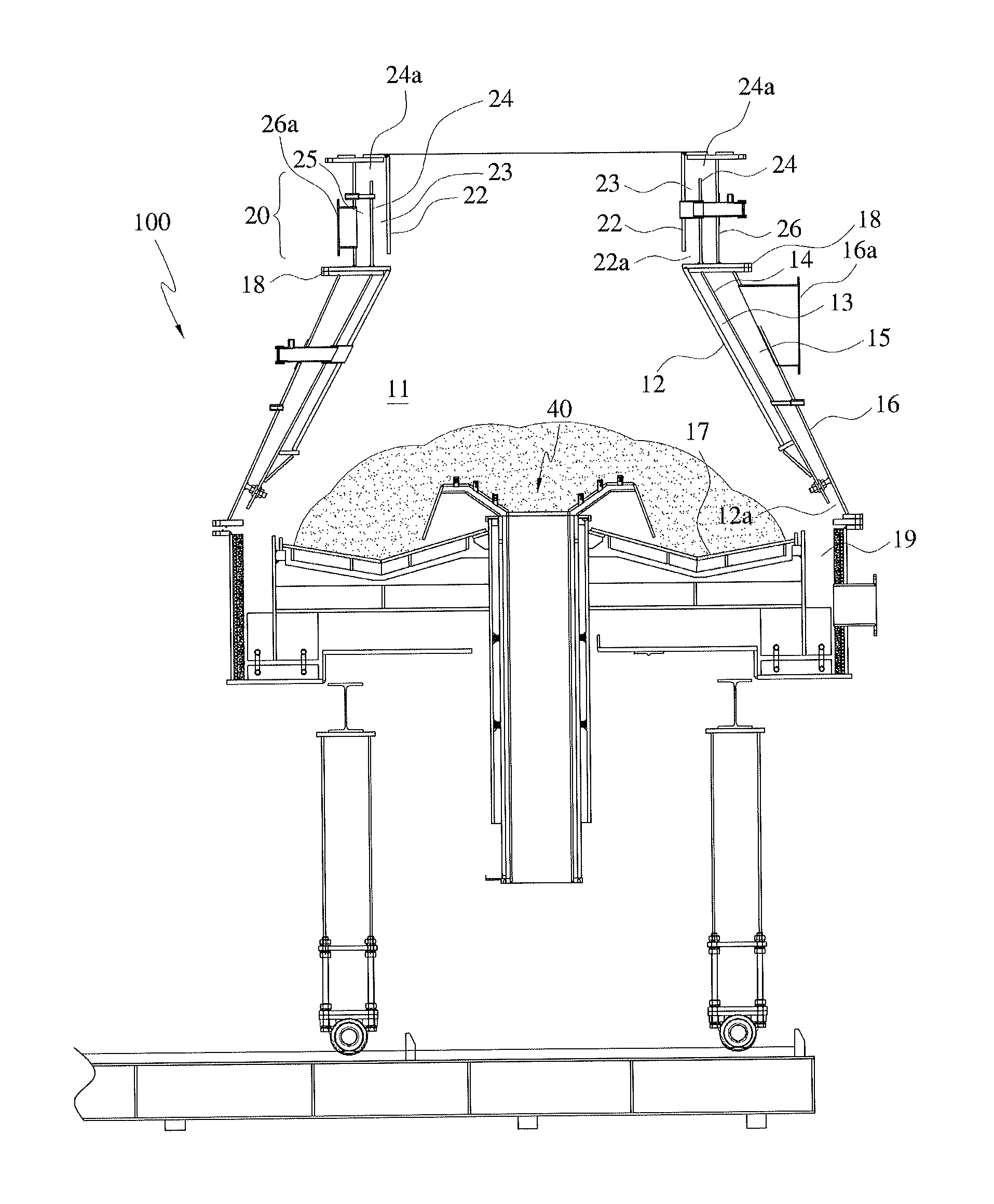
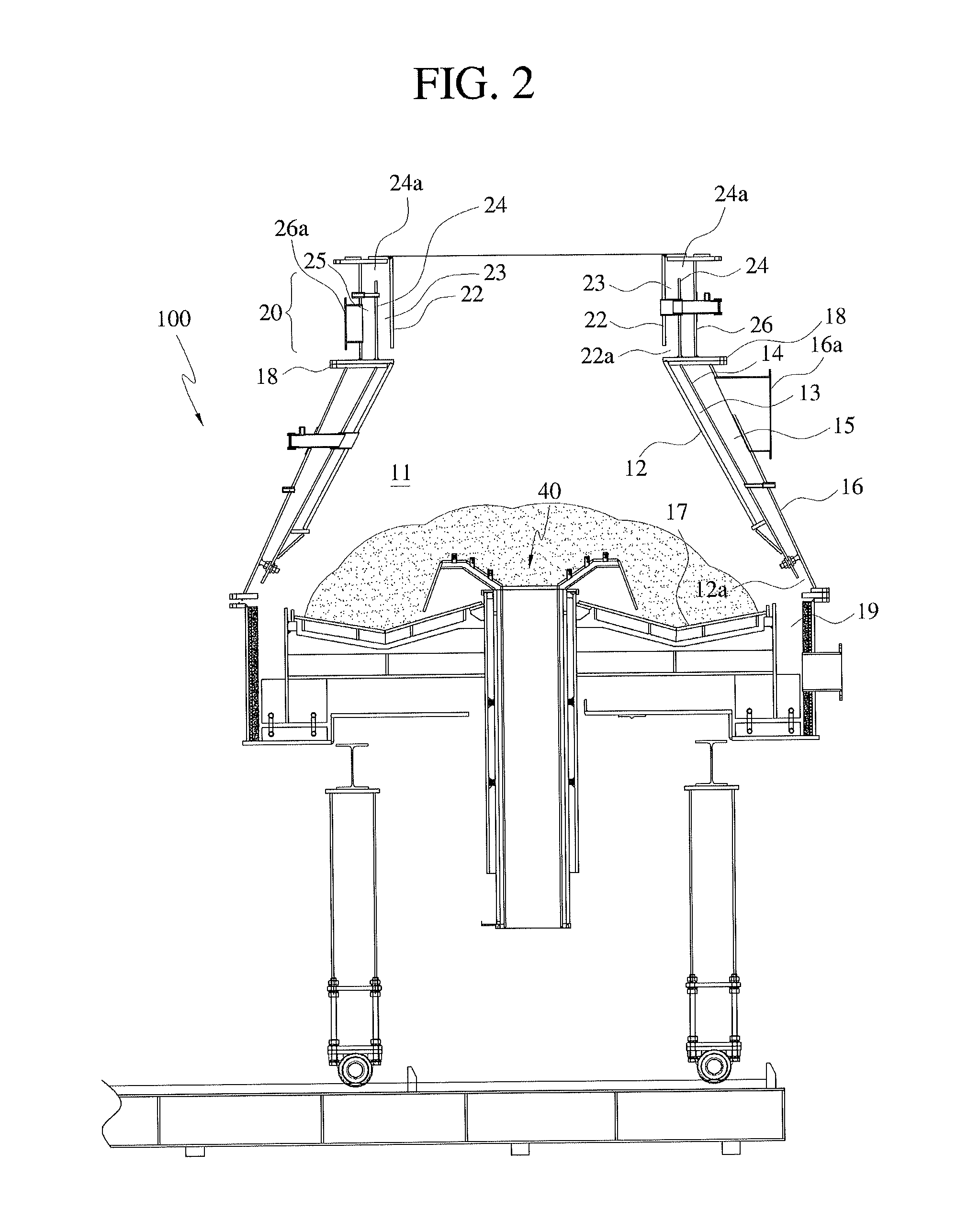
[0031]FIG. 2 is a cross-sectional view schematically showing a combustion apparatus according to an embodiment of the present invention. FIG. 3 is a cross-sectional view showing one side of a combustion vessel of FIG. 2. FIG. 4 is a schematic diagram showing a process that discharged cooling water is introduced into a boiler. FIG. 5 is a cross-sectional view showing a fuel supply unit of FIG. 2.

[0032]A combustion apparatus according to a preferred embodiment of the present invention, includes a combustion vessel 100 that burns a fuel therein and generates combustion gases of high temperature generated by combustion, and collects heat from the high temperature combustion gases using a boiler.

[0033]First, the combustion vessel 100 is formed in a cylindrical shape, and contains and burns a solid fuel therein. The combusti...


PUM


Abstract

A combustion apparatus includes a cylindrical combustion chamber surrounded by an inner wall. A cooling chamber comprises an intermediate wall spaced from the inner wall. Cooling water flows in and out lower and upper sides of the intermediate wall, to cool the inner wall by the cooling water that flows into a space formed between the inner and intermediate walls of the cooling chamber. A lateral combustion air supply chamber comprises an outer wall spaced from an outer side of the intermediate wall. Combustion air is supplied at an upper side of the outer wall to thereby make the air in a tangential direction with respect to the cylindrical outer wall turn and fall in a space formed between the intermediate wall and the outer wall, so that the combustion air is supplied to the combustion chamber via an opened lower portion of the lateral combustion air supply chamber.

Description

CROSS-REFERENCE TO RELATED APPLICATIONS AND CLAIM TO PRIORITY[0001]This application is related to application number 20-2010-7716, filed Jul. 22, 2010, and application number 10-2010-79534, filed Aug. 17, 2010, both in the Republic of Korea, the disclosures of which are incorporated herein by reference and to which priority is claimed.FIELD OF THE INVENTION[0002]The present invention relates to a heat collecting combustion apparatus, and more particularly, to a heat collecting combustion apparatus that collects heat of combustion that is generated by burning a solid fuel and so on in a combustion chamber and uses the collected heat as a recovery energy source.BACKGROUND OF THE INVENTION[0003]In general, industrial facilities that require industrial hot water, steam or gas of high temperature use a combustion apparatus that ignites and burns fuel in a combustion vessel to thus generate thermal energy, respectively. In addition, solid fuels such as RDF (Refuse Derived Fuel) that is ma...

Claims


Application Information

Patent Timeline
Patent Type & Authority Applications(United States)
IPC IPC(8): F22B37/14F22B17/16
CPCF23B40/04F23M5/08F23K3/14F23G2205/121
Inventor KIM, SANG KWON
Owner KIM SANG KWON
Why Eureka
Try Eureka