Common Field Magnetic Susceptors

Inactive Publication Date: 2012-01-26
LASKO STEPHEN B
View PDF4 Cites 10 Cited by
  • Summary
  • Abstract
  • Description
  • Claims
  • Application Information

AI Technical Summary

Benefits of technology

[0005]The apparatus of this invention presents a continuous melting method for electrically non-conductive particulate materials that can be started and stopped, as melted material demand is required. The process requires less power and does not degrade the material in the melting apparatus. When the heat of the susceptor is maintained at the target melt temperature of the material, flow volume is dependent on the viscosity of the melted material. Material presented to a surface of the perforated susceptor will flow through this interface only as fast as the material thermal conductivity will allow. Applying pressure to the material at this interface is of minor consequence to aid the speed of the process. Therefore, the process maximum volume is directly related to the surface area of the susceptor in contact with the material. The invention maximizes the melt surface area within a small envelope.

Problems solved by technology

Thermoplastic materials are poor thermal conductors.
If tank wall surface temperatures are allowed to exceed the material application temperature to expedite melting, material degradation will occur.
Many materials held at application temperature for an extended period will degrade in performance and foul the application apparatus.
Both of these applications experience overheating and start up delay, and are energy inefficient.

Method used


Image

  • Common Field Magnetic Susceptors
  • Common Field Magnetic Susceptors
  • Common Field Magnetic Susceptors

Examples


Embodiment Construction

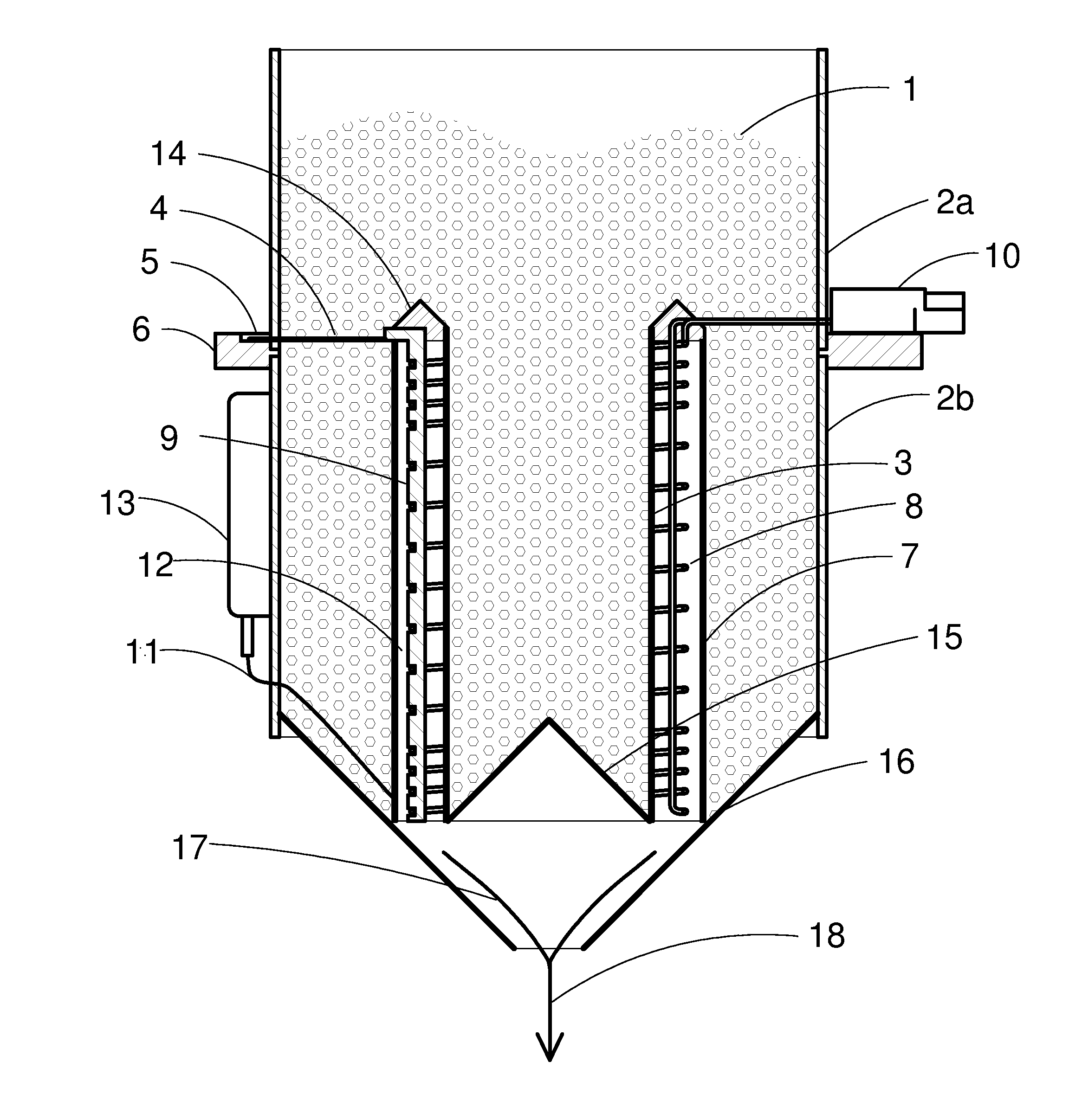
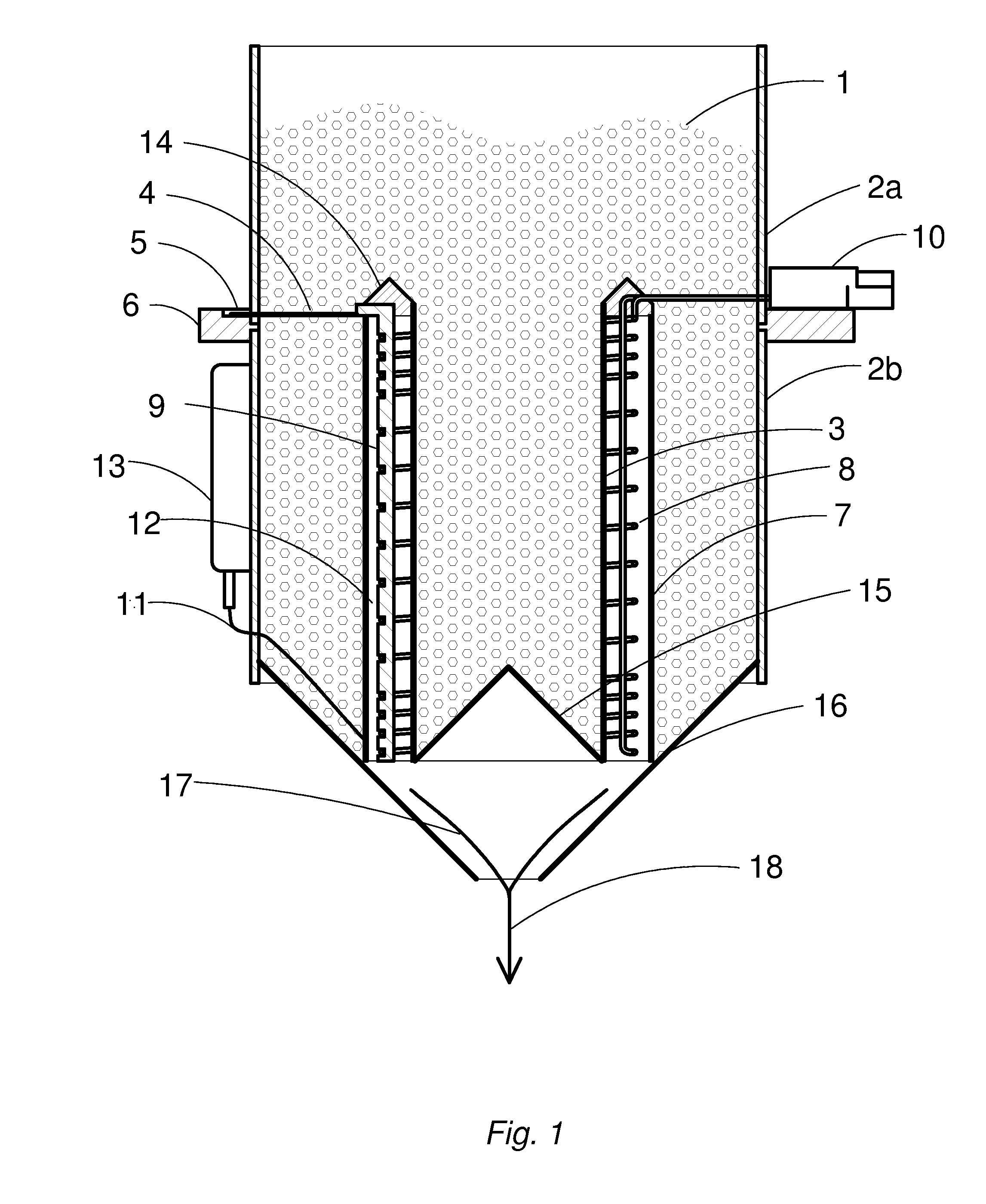
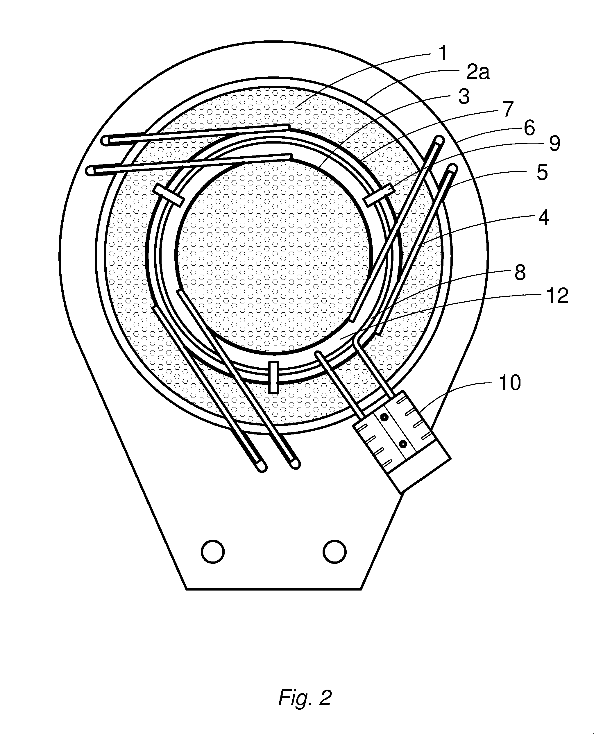
[0011]The major elements of this invention are illustrated in proportion and position in cross sectional view FIG. 1 and top view FIG. 2. Thermoplastic pellets 1 are continuously fed to a cylindrical containment vessel 2b with extension 2a acting as a removable reservoir. An inner susceptor 3, constructed of 20 ga. perforated steel, shaped as a cylinder, is suspended by three steel rods 4 that nest in locating slot 5 on support platform 6. An outer susceptor 7 of similar construction is coaxially positioned by support platform 6. A magnetic field inductor coil 8 is suspended in the annulus between susceptors 3 and 7 by three spacers 9 that rest on the upper edge of the outer susceptor 7. The thickness of the susceptor material is chosen to minimize the latent heat on power off. It dissipates into only those pellets contacting the susceptors. This allows an initial and subsequent restarts of melt flow within a few seconds.

[0012]Inductor coil 8 is constructed of solid 14 ga. bare copp...


PUM


Abstract

Thermoplastic pellitized materials are melted in gravity flow through coaxially oriented perforated cylindrical metal susceptors. The susceptors are equally energized by the interception of a common magnetic field formed by a high frequency powered inductor coil.

Description

FIELD OF THE INVENTION[0001]Cylindrical susceptors intercept a high frequency magnetic field to melt pellet form thermoplastic materials. A multi-turn magnetic induction coil and two perforated metal susceptors are vertically oriented on the same axis. A smaller diameter susceptor is placed in the coil interior and a larger diameter susceptor is placed on the coil exterior in coaxial location. When a current flows in the inductor coil, a toroid shaped magnetic field is formed. A current is induced in the field susceptors that generates controlled heat. Pelletized thermoplastic material is continuously gravity fed to fill the interior susceptor. Material is similarly fed to cover the exterior surface of the outer susceptor. Heat induced in the susceptors melts the material in contact with both surfaces. Melted material flows in the annulus between the susceptors to exit at the bottom end with minor thermal exposure time.BACKGROUND OF THE INVENTION[0002]Current methods of melting pell...

Claims


Application Information

Patent Timeline
IPC IPC(8): H05B6/10
CPCH05B6/107
Inventor LASKO, BERNARD
Owner LASKO STEPHEN B
Why Eureka
Try Eureka