Process for manufacturing a micromechanical structure having a buried area provided with a filter

a micromechanical structure and filter technology, applied in the direction of positive displacement liquid engine, laboratory glassware, membranes, etc., can solve the problems of long processing time, high cost, and complicated back-end and bonding operations

Inactive Publication Date: 2012-01-26
STMICROELECTRONICS SRL
View PDF4 Cites 12 Cited by
  • Summary
  • Abstract
  • Description
  • Claims
  • Application Information

AI Technical Summary

Benefits of technology

[0017]One embodiment of the present disclosure is a process that enables formation, in a body of semiconductor material, of buried areas provided with structures for filtering of contaminating impurities, and that is simple and inexpensive to implement.

Problems solved by technology

These manufacturing processes have, however, certain drawbacks that do not enable full exploitation of the characteristics thereof, amongst which:the techniques of back processing, and the subsequent operations of bonding between different bodies, entail generally the generation of undesirable particles and contaminants, which can jeopardize operation of the final microfluidic device; andthe back-end and bonding operations are in general complex, costly, and generally require long processing times.
In particular, the problem of contamination from external particles, which is not due only to the aforesaid manufacturing operations and to the residue of processing, but also to the presence for other reasons of external particles that can interact with the buried area, is particularly felt, in so far as this contamination can jeopardize the performance of the microfluidic devices or proper execution of the operations of delivery or passage of the fluids associated thereto.
This solution is not, however, optimized from the standpoint of simplicity and economy of the manufacturing process, for example because it requires complex steps of coupling of the filter to structures formed separately, it requires to comply with specifications of mechanical and / or optical alignment, and moreover it does not enable in any case reduction of the contaminations in the manufacturing process of the buried areas.
These solutions suffer from further disadvantages, amongst which: the process of bonding of the various bodies suffers from misalignment inaccuracy, the value of which (for example + / −20 μm) may not enable formation of sufficiently small filtering pores (for example of a diameter of 0.5 μm); during the bonding operation, the distance between the vertical pillars and the body facing them may not be sufficiently repeatable for enabling an adequate filtering action; and furthermore, in order to obtain adequate flows of fluids, the buried channels have, for example, a height of some tens of microns (for example, a height of 50 μm), with the consequent fragility of the aforesaid pillars that extend vertically from the bottom wall to the top wall of the channels (failure of the pillars can jeopardize the filtering action and can itself cause impurities in the flow of the fluids).

Method used


Image

  • Process for manufacturing a micromechanical structure having a buried area provided with a filter
  • Process for manufacturing a micromechanical structure having a buried area provided with a filter
  • Process for manufacturing a micromechanical structure having a buried area provided with a filter

Examples


Embodiment Construction

[0026]A manufacturing process according to one embodiment of the present disclosure is now described; it is to be noted that some initial steps of the manufacturing process are, at least in part, based upon the processes described in U.S. Pat. No. 7,294,536 and U.S. Application Publication No. 2008 / 261345, which are incorporated herein by reference.

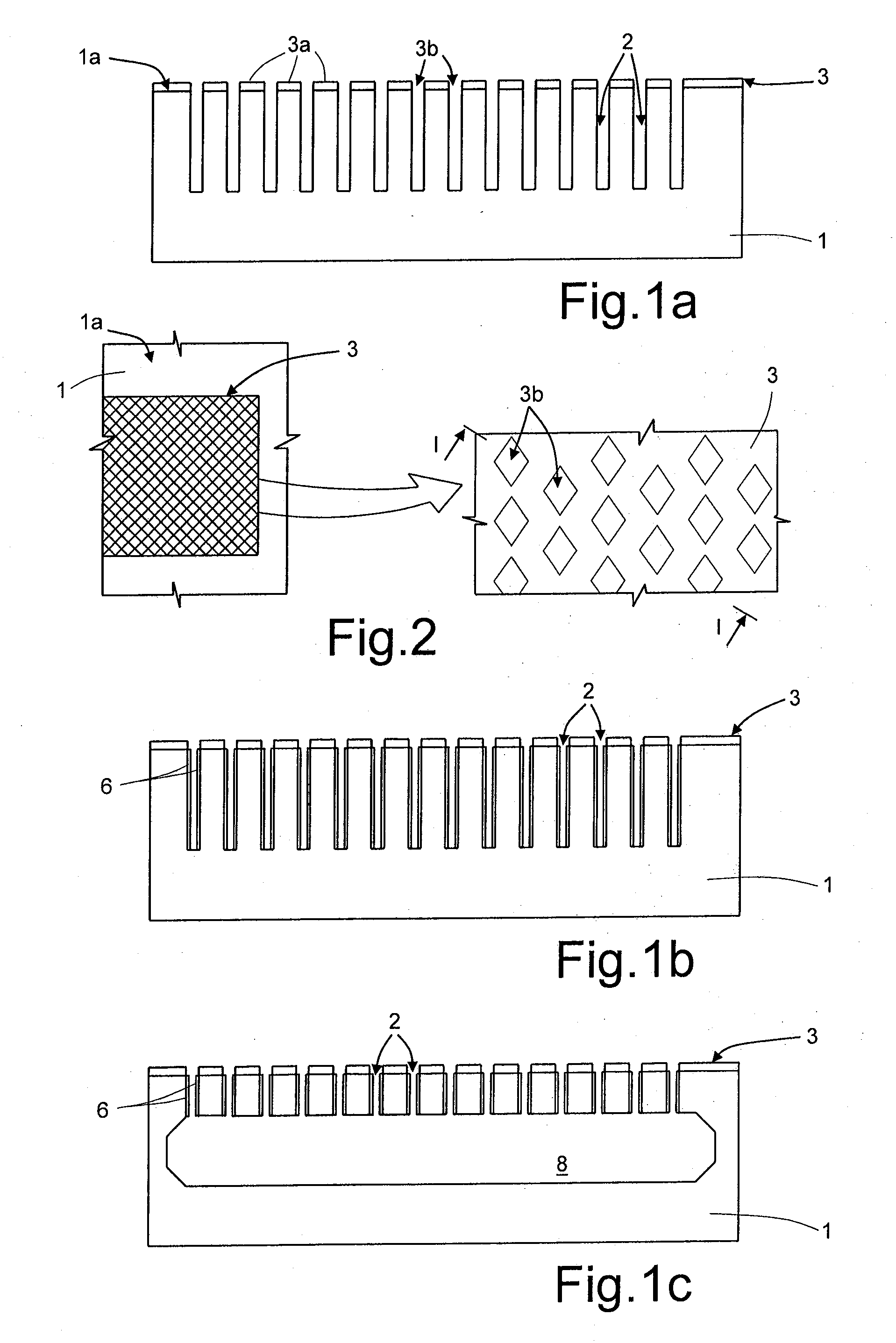
[0027]As shown in FIG. 1a (not drawn to scale, as neither are the subsequent figures), an initial step of the manufacturing process envisages formation, within a substrate 1 of monocrystalline silicon, of a plurality of trenches 2. The trenches 2 are dug through a surface portion of the substrate 1 by means of known techniques of masking and anisotropic chemical etching.

[0028]In particular, a mask 3 is formed on a top surface 1a of the substrate 1, the mask being made of a material resistant to chemical etching, for example photoresist.

[0029]The mask 3 extends (see also the top plan view of FIG. 2) over an area having a shape substantiall...


PUM


Abstract

A process for manufacturing a micromechanical structure envisages: forming a buried cavity within a body of semiconductor material, separated from a top surface of the body by a first surface layer; and forming an access duct for fluid communication between the buried cavity and an external environment. The method envisages: forming an etching mask on the top surface at a first access area; forming a second surface layer on the top surface and on the etching mask; carrying out an etch such as to remove, in a position corresponding to the first access area, a portion of the second surface layer, and an underlying portion of the first surface layer not covered by the etching mask until the buried cavity is reached, thus forming both the first access duct and a filter element, set between the first access duct and the same buried cavity.

Description

BACKGROUND[0001]1. Technical Field[0002]The present disclosure relates to a process for manufacturing a micromechanical structure having a buried area provided with a filter. In one embodiment, the micromechanical structure is formed in a body made of semiconductor material, in particular silicon, using micromachining techniques and finds advantageous use, for example, for microfluidic applications.[0003]2. Description of the Related Art[0004]As is known, in the semiconductor industry micromachining techniques enable manufacturing of micromechanical or MEMS (microelectromechanical systems) structures, which have a wide range of applications.[0005]In particular, in the microfluidic field, it is common to manufacture structures including buried areas (for example channels, chambers, or cavities) within a silicon substrate (or other semiconductor material body), which are for example used for enabling passage of fluids, such as drugs that are to be administered to a patient or inks use...

Claims


Application Information

Patent Timeline
Patent Type & Authority Applications(United States)
IPC IPC(8): H01L29/84H01L21/02
CPCB01D67/0062B01D71/02B01D2325/021B01D2325/028B01L3/502707F04B19/006B01L2300/0681B81B2201/10B81C1/00071B81C1/00087B81C2201/0133B01L3/502753B81C2201/0116B81C1/00119B81C2201/0157
Inventor FERRERA, MARCOPERLETTI, MATTEOVARISCO, IGORZANOTTI, LUCA
Owner STMICROELECTRONICS SRL
Why Eureka
Try Eureka