

Method for Client Data Transmission Through a Packet Switched Provider Network
a packet switched provider and client technology, applied in the field of telecommunications, can solve problems such as adversely affecting the network recovery time, and achieve the effect of fast recovery
- Summary
- Abstract
- Description
- Claims
- Application Information
AI Technical Summary
Benefits of technology
Problems solved by technology
Method used
Image

Examples
first embodiment
[0049]In the first embodiment, use is made of Ethernet OAM (Operation, Administration, and Maintenance) functions. In particular, a new Ethernet OAM Protocol Data Unit (PDU) for the address withdrawal message is defined. The AWM can be defined either as a new standard OAM PDU or as a vendor-specific VSM OAM PDU, as defined in ITU-T Y.1731, which is incorporated by reference herein. An example of a new standard OAM PDU is shown in FIG. 3. An alternative example of a vendor-specific OAM PDU is shown in FIG. 4.
[0050]In FIG. 4, the AWM VSM message sub-type will be identified by a vendor specific OUI field and a SubOpCode field which may be chosen for example as 0x01 and indicates the MAC withdrawal purpose of the OAM PDU. The Multicast DA Class 2, as defined in Y.1731, is used for the AWM in order to make it being processed in any provider bridge nodes that needs to perform MAC flushing. The specific address of the Multicast DA Class 2 is chosen according to the MEL (MEL: MEG Level; MEG...
second embodiment
[0062]In a second embodiment, the AWM is defined as a specialized new protocol. In particular, a new EtherType is defined for carrying the Address Withdrawal Message over Ethernet frames. The AWM frame format is shown in FIG. 6.
[0063]The AWM can be defined either as a new standard EtherType, as a vendor-specific EtherType or as a combination of a vendor-specific EtherType with Sub-Type. An Ethernet switching node when receiving such a packet processes it as an AWM according to the EtherType or the field(s).
[0064]The MAC destination address should allow the neighbor node to identify the frame as an AWM frame and process it locally. There are different alternatives:[0065]All Provider Bridges MAC @[0066]Another Reserved Multicast MAC Address[0067]A proprietary multicast MAC Address.
[0068]The first two options (All Provider Bridges MAC @ or another reserved multicast MAC address) are more appropriate if a standard solution is developed although they can be also used if a proprietary so...
third embodiment
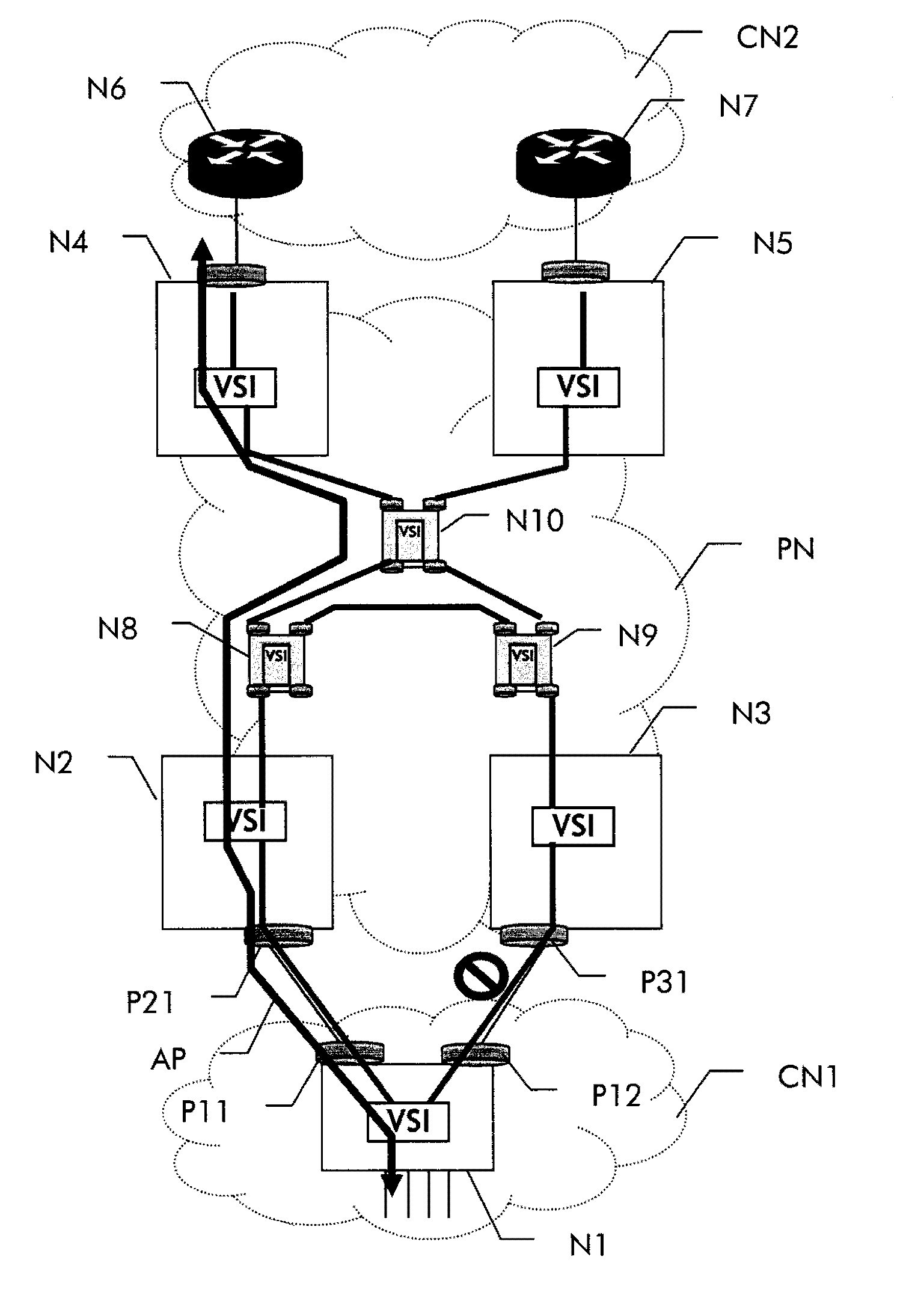
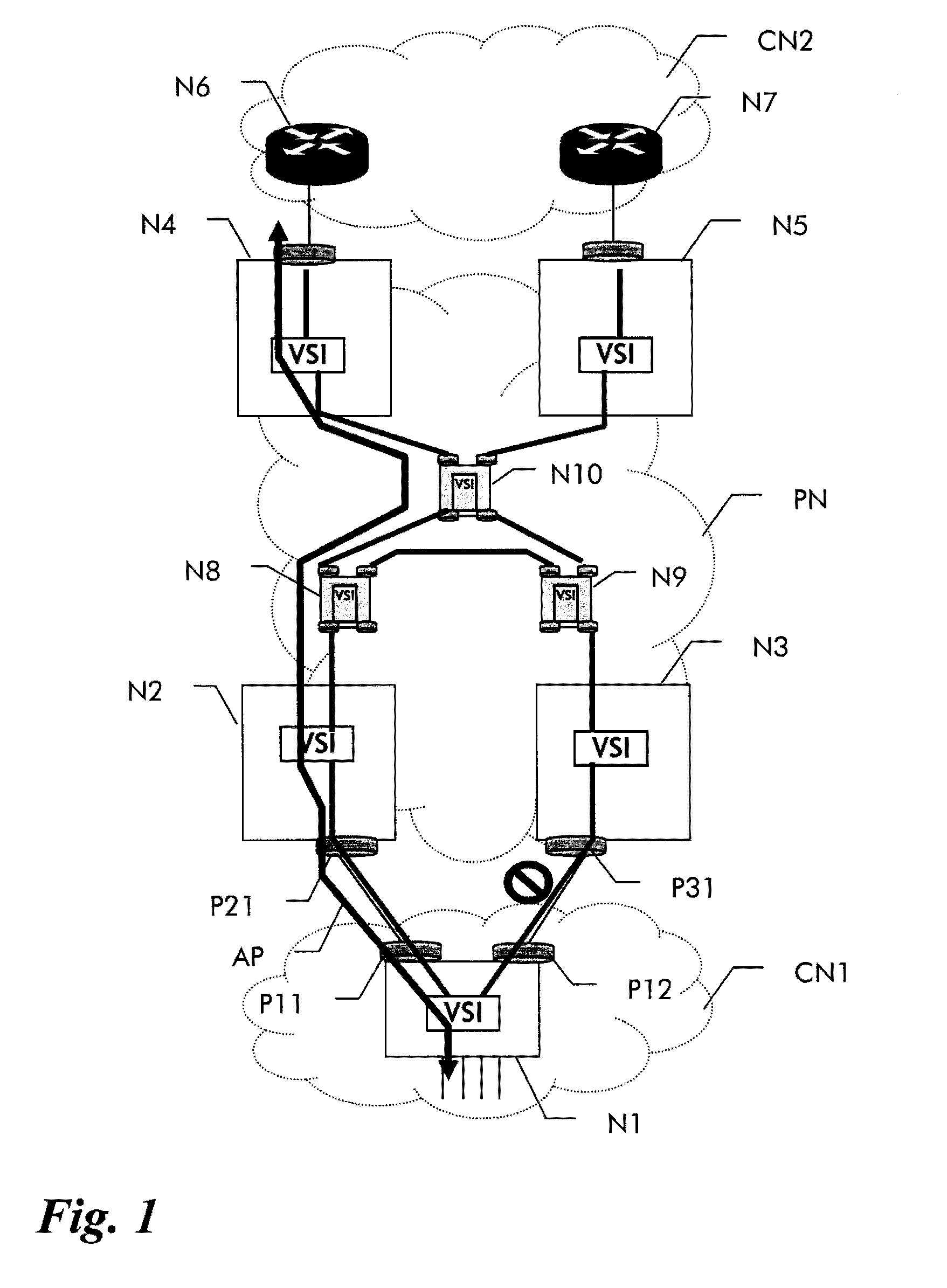
[0092]In the following, embodiments for address flushing in the different transmission technologies will be described in more detail. In a third embodiment shown in FIG. 7, the provider network relies on VPLS technology. As in FIGS. 1 and 2a-c, a first customer edge node NE_1 is connected via the provider network PN to a second customer edge (CE) node NE_6. The CE nodes NE_1, NE _6 are connected via Ethernet access links to provider edge (PE) nodes NE_2, NE_4, respectively. Three intermediate provider nodes NE_a, NE_b, and NE_c are shown by way of example in FIG. 7. An MPLS LSP tunnel is established between NE_2 and NE_b via NE_a and another MPLS LSP tunnel is established between NE_b and NE_4 via NE_c. Over these MPLS LSP tunnels, a VPLS multi-segment pseudowire MS-PW is established between NE_2 and NE_4, which provides the connectivity between the VSIs on the VPLS PEs (NE_2 and NE_4) for the transport of the customer signal through the provider network.
[0093]As in FIG. 1, a redund...
PUM
 Abstract
Description
Claims
Application Information