Methods and systems for an engine emission control system

a technology of emission control system and engine, which is applied in the direction of arsenic compounds, silicon compounds, separation processes, etc., can solve the problems of affecting the no oxidation function of the catalyst, the temperature control strategy of the emission control device may not be achieved, and the failure to meet emissions compliance, etc., to achieve the effect of improving the capacity of the third layer, improving the formation of no2, and increasing the capacity of the second layer with the hc trap

Active Publication Date: 2012-02-02
FORD GLOBAL TECH LLC
View PDF5 Cites 80 Cited by
  • Summary
  • Abstract
  • Description
  • Claims
  • Application Information

AI Technical Summary

Benefits of technology

[0005]In one example, some of the above issues may be at least partially addressed by a layered emission control system coupled to a vehicle engine exhaust manifold. In one embodiment, the layered system comprises a first, upper layer including a first, oxidizing catalyst, a second, intermediate layer including a HC trap for trapping exhaust HCs, and a third, lower layer including a second, different oxidizing catalyst. The second layer may be positioned between the first and third layers, and all the layers may be layered on, and supported by a substrate support. In this way, various formulations may be layered on a substrate in a selected order to enable various emission control functions to be grouped within spatial constraints to provide synergistic benefits.
[0006]For example, an exhaust emission control system may include a layered emission control device upstream of one or more NOx catalysts and particulate filters. In one example, the layered emission control device may be a layered diesel oxidation catalyst system wherein a plurality of layers are layered on, and supported by a substrate support. A first, upper layer may include a first, oxidizing catalyst, such as a diesel oxidation catalyst (DOC), for oxidizing exhaust hydrocarbons (HCs) and generating an exotherm for downstream particulate filters or HC traps. For example, exhaust HCs may be oxidized to periodically generate an exotherm, such as to assist in regeneration of a downstream particulate filter. A second, intermediate layer may include a HC trap for trapping exhaust HCs. A th

Problems solved by technology

However, the inventors herein have identified potential issues with such systems.
As one example, the various functions may compete and/or interfere with each other.
However, the hydrocarbon and carbon monoxide oxidizing function of the diesel oxidation catalyst may interfere with the NO oxidation function of the catalyst.
As a result, even with different configurations, emissions

Method used


Image

  • Methods and systems for an engine emission control system
  • Methods and systems for an engine emission control system
  • Methods and systems for an engine emission control system

Examples


Embodiment Construction

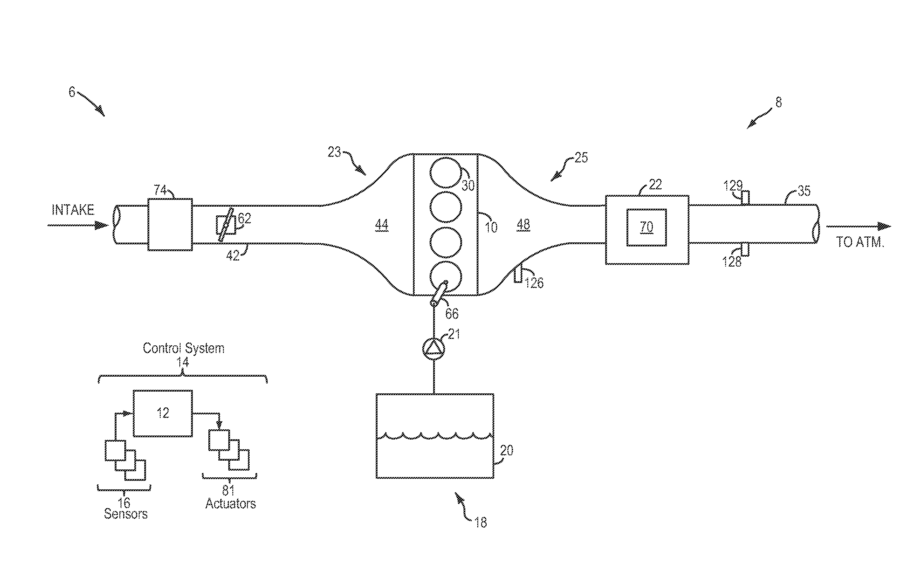
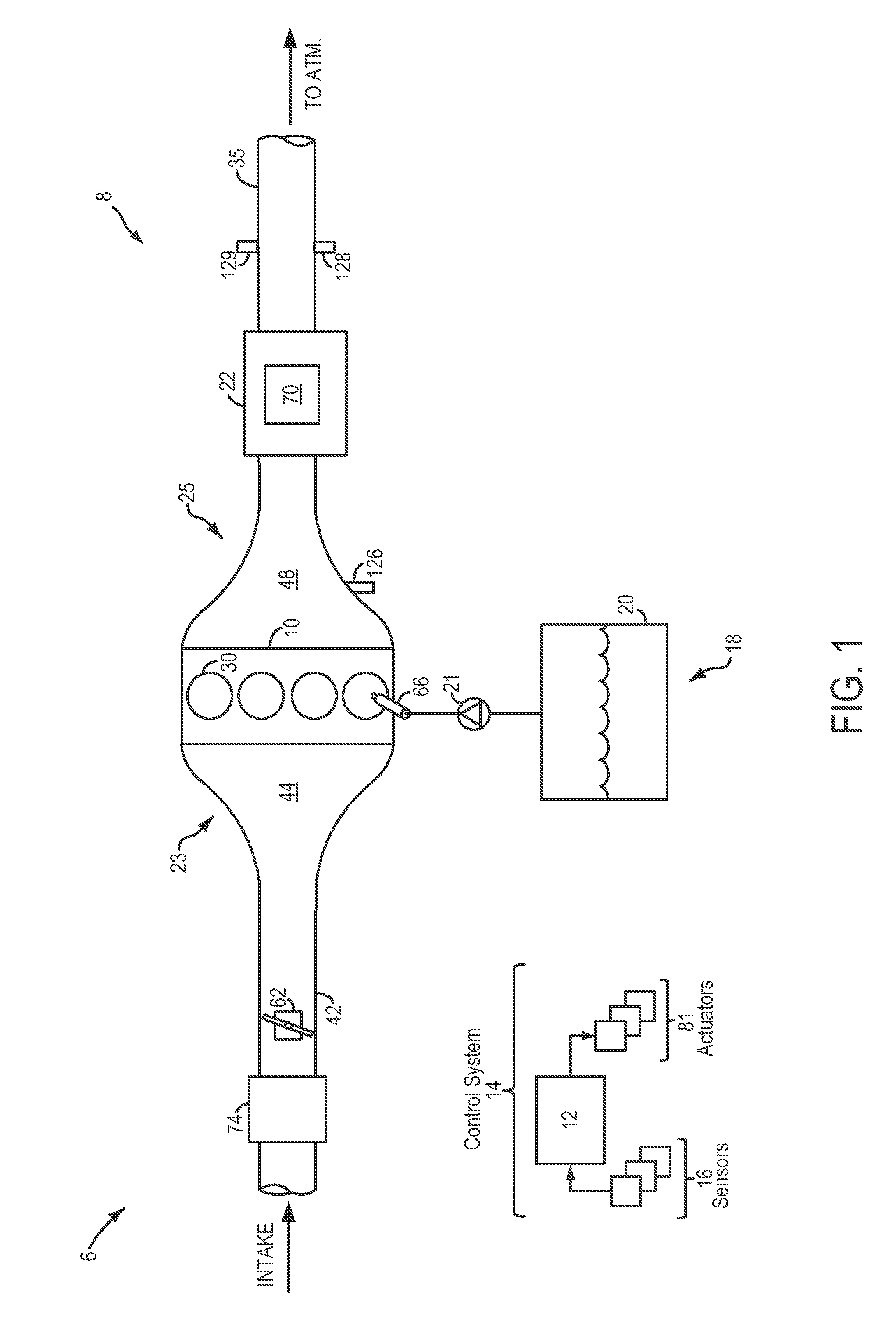
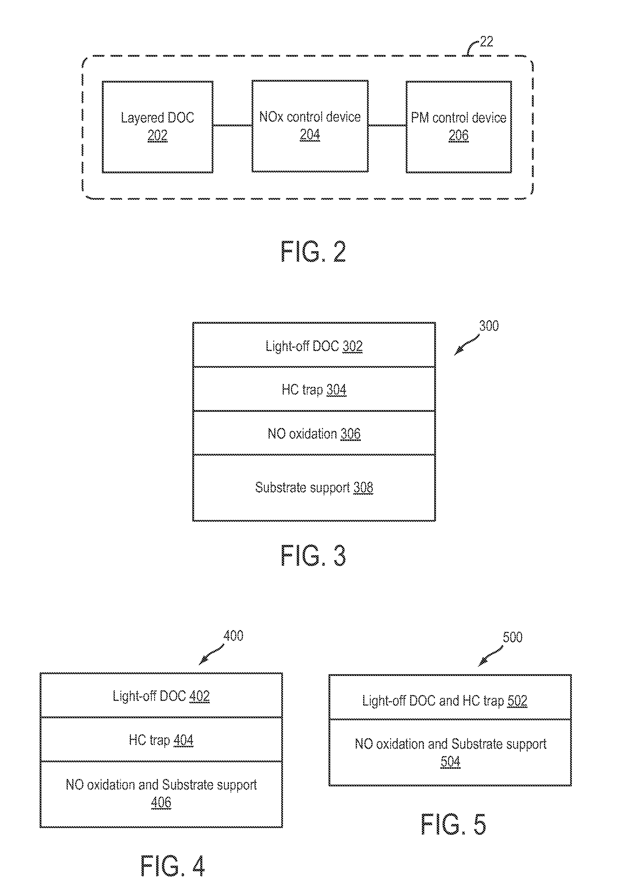
[0013]The following description relates to systems and methods for a layered emission control device coupled to the exhaust manifold of an engine system, such as the engine system of FIG. 1. The layered emission control device may be a layered diesel oxidation catalyst (DOC) system, as shown in FIG. 2, positioned upstream of one or more other emission control devices, such as one or more NOx reducing catalysts and particulate matter (PM) filters coupled to the engine exhaust manifold. The various layers of the layered device may include different formulations for enabling different emission control functions to be performed within the spatial constraints of the device. The various formulations may be layered, as shown in FIGS. 3-5, so as to reduce functional interference while enabling functional synergies. As shown in FIG. 6, exhaust gas may be passed over and through the layered device to retain and oxidize exhaust hydrocarbons and raise the exhaust temperature, while oxidizing ex...


PUM

PropertyMeasurementUnit
Temperatureaaaaaaaaaa
Porosityaaaaaaaaaa

Abstract

Systems and methods are provided for a layered emission control device coupled to an exhaust manifold. Various formulations may be incorporated in a plurality of layers of the device to enable various emission control functions to be grouped within spatial constraints. The layers may be organized to reduce functional interference and improve functional synergy between the various emission control functions.

Description

FIELD[0001]The present application relates to methods and systems for emission control of a vehicle with a diesel oxidation catalyst having more than one catalytic environment.BACKGROUND AND SUMMARY[0002]In an effort to meet stringent federal emissions regulations, vehicle engines may be configured with an emission control system including various emission control devices, such as three-way catalysts, diesel oxidation catalysts, particulate filters, NOx catalysts, and hydrocarbon (HC) traps. The various emission control devices may be arranged in different configurations.[0003]One example configuration is shown by Maaseidvaag et al. in U.S. Pat. No. 6,167,696. Therein, a three-way catalyst is included upstream of a HC trap, a NOx trap and an electrically heated catalyst. Another example configuration is shown by Yamato et al. in U.S. Pat. No. 7,181,903. Therein, a three-way catalyst is included downstream of a NOx trap and a plasma reactor containing a HC trap. Based on the specific...

Claims


Application Information

Patent Timeline
IPC IPC(8): F01N3/18F01N3/035F01N3/10
CPCB01D53/90F01N13/009B01D53/9477B01D2251/2062B01D2251/2067B01D2255/1021B01D2255/1023B01D2255/104B01D2255/106B01D2255/2073B01D2255/20761B01D2255/50B01D2255/65B01D2255/9025B01D2255/91B01D2255/912F01N3/035F01N3/0814F01N3/0835F01N3/0842F01N3/103F01N3/106F01N2510/0684B01D53/9454F01N13/0097B01D53/9468
Inventor LAMBERT, CHRISTINE KAYDOBSON, DOUGLAS ALLEN
Owner FORD GLOBAL TECH LLC
Why Eureka
Try Eureka