
Operating state monitoring of support apparatus of an elevator system

a technology of operating state monitoring and support apparatus, which is applied in the direction of elevators, transportation and packaging, etc., can solve the problems of difficult detection of reliable trigger values, dangerous states, and problems such as counterweight, and achieve the effects of less adjustment and maintenance, improved detection of slack support, and less maintenan

Active Publication Date: 2012-02-02
INVENTIO AG
View PDF11 Cites 14 Cited by
  • Summary
  • Abstract
  • Description
  • Claims
  • Application Information

AI Technical Summary

Benefits of technology

[0010]An object of the present invention is to propose a monitoring device for the operating state of the single or plural support means of an elevator installation, which is distinguished by a construction which is simpler, involves less adjustment and maintenance and is thus more economic and which avoids the stated disadvantages of the prior art, particularly to guarantee an improved detection of a slack support means due to a disturbance.
[0016]Proposed solutions from the prior art, such as, for example, disclosed in International published specification WO-A1-2007 / 144456, similarly propose an abutment for the normal operational state when the support means is under load. The relief of the support means of load leads, due to the spring biasing force, to a movement of a transmission element away from the abutment to a limit switch. The deflecting roller monitoring device according to the invention thereagainst provides a sensor which is switched on in the normal operational state. However, as soon as the deflecting roller is urged by the force store element away from the abutment, the signal changes. Because transiting a path to a limit switch is thus eliminated, the accuracy of detection is increased and makes the monitoring device usable for wider load ranges. The load range fluctuates between the empty elevator car in the highest position, thus with the support means wound up to the maximum, and fully loaded or even over-loaded elevator car in the lowermost position, thus with the support means unwound to maximum extent.
[0017]A first more detailed variant of embodiment of the described basic variant provides at both sides of the drive pulley, i.e. not only at the support means section between the drive pulley and the first point of engagement of the support means with the elevator car, but also at the support means section between the drive pulley and the first point of engagement of the support means with the counterweight, a respective deflecting roller according to the invention. As a result, not only when the counterweight rests on the shaft floor buffers or when jamming of the counterweight occurs in its downward movement, but also when the elevator car rests on corresponding shaft floor buffers, further upward movement of the respective counter-load (elevator car or counterweight) can be avoided.
[0018]A further variant of embodiment relates to an elevator installation in which the elevator car is underslung by support means, i.e, the elevator car stands on deflecting rollers, which support it, in a loop formed by the support means. In the case of parallelly extending support means preferably two deflecting rollers according to the invention with a force store element and a sensor are respectively arranged at the lower edges of the elevator car. In this manner it is achieved that a relief of load or slackening in the support means is detectable and a signal for stopping the drive and the drive pulley or for reversal of direction of the drive pulley can be issued. In particular, in this variant of embodiment it is advantageous that the monitoring device functions independently of the intrinsic weight of the support means loop.
[0020]In order that the sensors at the strut do not interpret a maximum unwinding of a support means section and the thereby arising relief of load as an instance of disturbance, the strut is preferably arranged between the drive pulley and a further, fixedly arranged counter-roller for the support means or between two further, fixedly arranged counter-rollers for the support means. These additional, fixed counter-rollers are preferably easy running and produce little contact friction at the support means.
[0028]A further advantage of the combination of deflecting roller monitoring device according to the invention with the load moment sensor monitoring device according to the invention is, apart from the fact that several kinds of disturbance situation as before are detectable, the fact that the load sensors usually arranged in the shaft floor buffers can be eliminated.

Problems solved by technology

The same problem can arise with the counterweight if the elevator car should sit on the shaft floor buffers.
This lifting up of a load—be it the elevator car or the counterweight—at one side of the drive pulley without the provided counter-load at the other side of the drive pulley running conjunctively to freely rise is impermissible and can lead to dangerous states (dropping back of the elevator car or the counterweight).
It is disadvantageous with this solution that it is suitable only for elevator installations with a small conveying height and that there is no detection at the directly affected support means sections between drive pulley and support roller of the elevator car or between drive pulley and support roller of the counterweight.
The disadvantages of these two solutions according to the prior art are on the one hand the constructional outlay and on the other hand the difficulty of detecting a reliable trigger value.
Particularly in the case of large conveying heights and thus lengthy support means sections the high intrinsic weight of the support means emerges as unfavorable inasmuch as a difference between loaded operating state of the support means and slack state of the support means is detectable only with difficulty.

Method used


Image

  • Operating state monitoring of support apparatus of an elevator system
  • Operating state monitoring of support apparatus of an elevator system
  • Operating state monitoring of support apparatus of an elevator system

Examples


Embodiment Construction

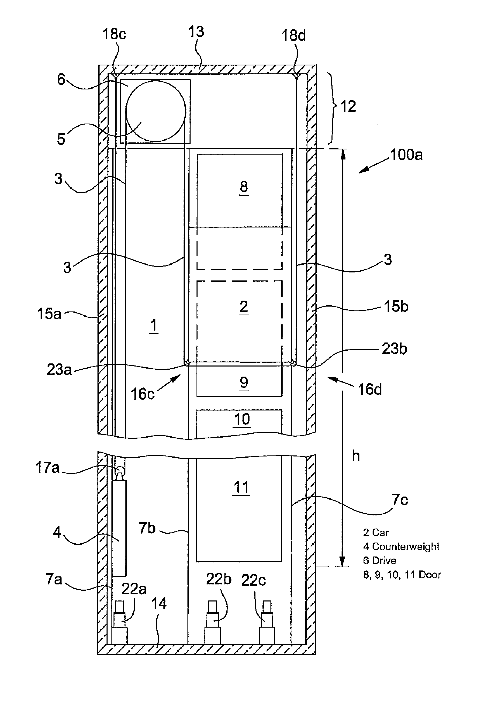
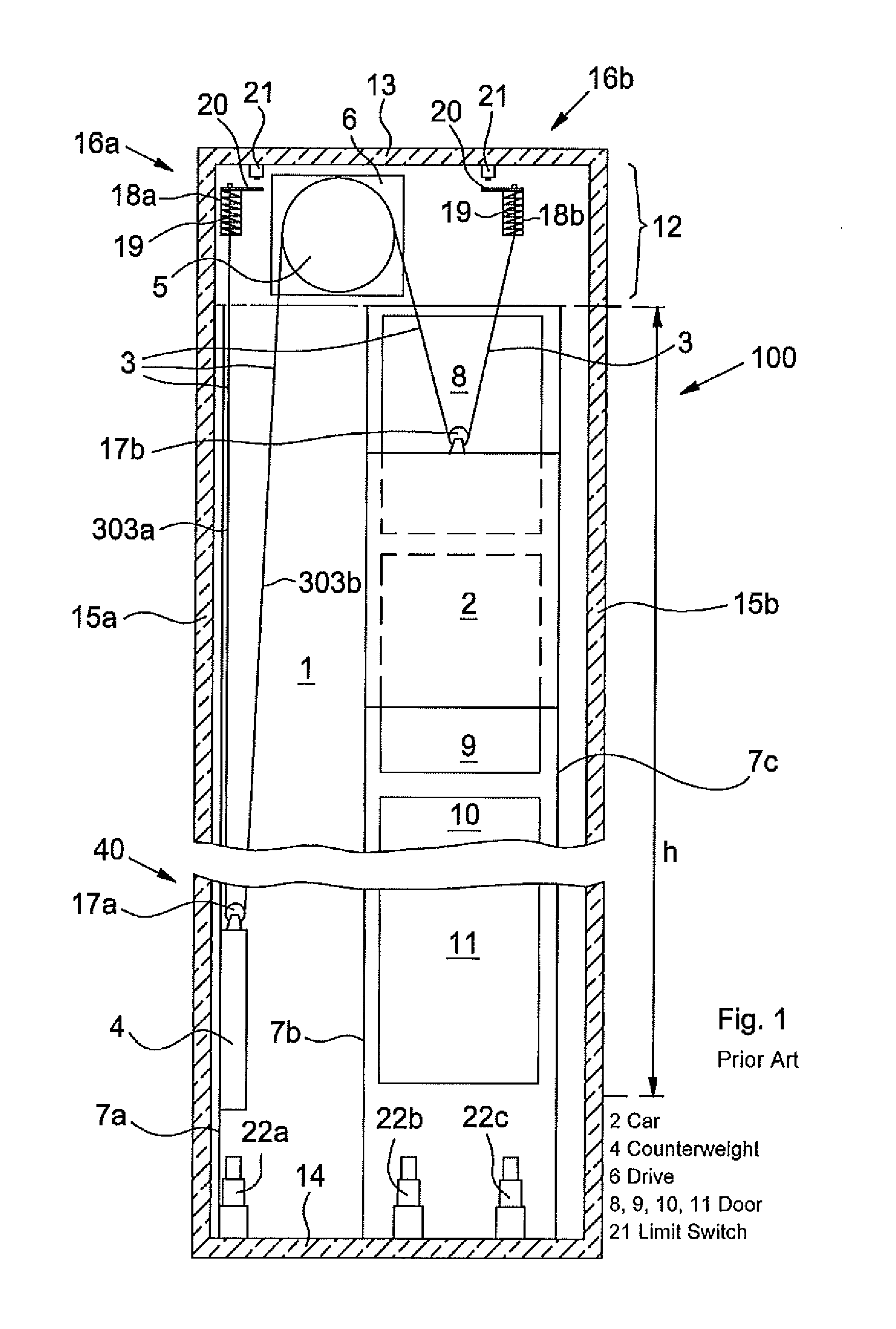
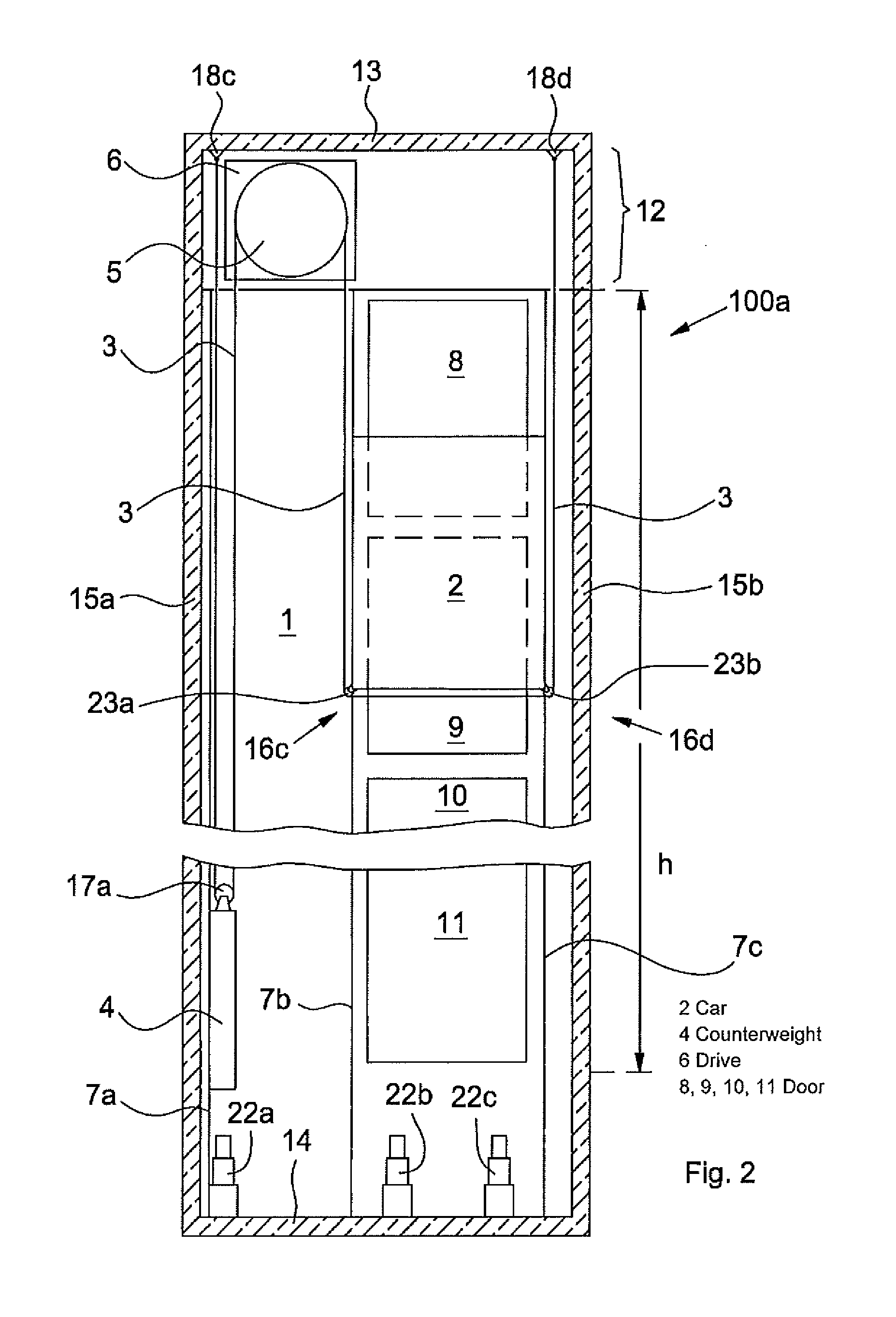
[0042]FIG. 1 shows an elevator installation 100 such as is known from the prior art. An elevator car 2 is arranged in the elevator shaft 1 to be movable and is connected by way of a support means or apparatus 3 with a movable counterweight 4. During operation the support means or apparatus 3 is driven by a drive pulley 5 of a drive unit 6, which is arranged in the uppermost region of the elevator shaft 1, for example in the shaft head 12 or in the engine room 12. The elevator car 2 and the counterweight 4 are guided by means of guide rails 7a or 7b and 7c extending over the shaft height.

[0043]The elevator car 2 can over a conveying height h serve an uppermost floor door 8, further floor doors 9 and 10 and a lowermost floor door 11. The elevator shaft 1 is formed from shaft side walls 15a and 15b, a shaft ceiling 13 and a shaft floor 14, on which a shaft floor buffer 22a for the counterweight 4 and two shaft buffers 22b and 22c for the elevator car 2 are arranged.

[0044]The support me...


PUM


Abstract

An elevator system includes at least one elevator car and at least one counterweight, which can be moved in opposite directions from each other on at least one guide track in an elevator shaft by a support apparatus guided over a traction sheave of a drive. At least one monitoring device detects a slackening of the support apparatus, wherein the monitoring device is disposed at a deflection roller for the support apparatus.

Description

FIELD OF THE INVENTION[0001]The present invention relates to an elevator installation in which at least one monitoring device or device for operational state monitoring of the or each support apparatus for the elevator car or for the counterweight is provided in an elevator installation.BACKGROUND OF THE INVENTION[0002]An elevator installation usually comprises an elevator car and at least one counterweight, which are moved in opposite sense in an elevator shaft. The elevator car and the at least one counterweight in that case run in or along guide rails and are supported by at least one support means, which is guided over a driving drive pulley. The support means usually consists of one or more sheathed steel cables, one or more synthetic fiber cables, one or more flat or profiled belts (wedge-ribbed belts) or a parallelly extending composite of the respectively mentioned constructions, in which each individual support means can be guided over a respective individual drive pulley.[...

Claims


Application Information

Patent Timeline
IPC IPC(8): B66B3/00
CPCB66B5/125B66B5/12
Inventor HENNEAU, PHILIPPE
Owner INVENTIO AG
Learn More