Sheet press molding method and method of manufacturing fuel cell separator

a fuel cell separator and molding method technology, applied in the direction of sustainable manufacturing/processing, final product manufacturing, electrochemical generators, etc., can solve the problems of large specific gravity of metal materials, insufficient corrosion resistance, brittle fracture, etc., to achieve high electrical conductivity, high strength, and thin thickness

Inactive Publication Date: 2012-02-02
SHOWA DENKO KK
View PDF3 Cites 52 Cited by
  • Summary
  • Abstract
  • Description
  • Claims
  • Application Information

AI Technical Summary

Benefits of technology

[0040]Since the sheet press molding method of the invention is a method in which a process is provided for forming a molded product having a recess and protrusion pattern portion, to which a recess and protrusion pattern is transferred, by pressurizing a sheet-shaped material including a resin composition and 60 vol. % to 95 vol. % of a filler using a pair of molds, at least one of which has a predetermined recess and protrusion pattern composed of recessed portions and protruding portions, and a pair of molds provided with a dummy pattern composed of dummy recessed portions or dummy protruding portions which offset the difference between the total volume of protruding portions formed on the inside and the total volume of recessed portions disposed between the protruding portions and the side surfaces of the inside and between the protruding portions on the inside is used as a pair of the molds, the volume of protruding portions in the molded product becomes the same as the volume of recessed portions in the molded product, and the softened sheet-shaped material pressurized on the protruding portions of the mold and pressed out is smoothly flowed into portions facing the recessed portions of the mold when performing the pressing process. As a result, according to the sheet press molding method of the invention, a molded product having a small plate thickness deviation can be obtained when the molded product is manufactured by press molding of a sheet-shaped material including a filler and a resin composition regardless of the sheet-shaped material includes a large amount of filler or has a refined recess and protrusion pattern.
[0041]In addition, since the method of manufacturing a fuel cell separator of the invention is a method in which a process is provided for forming a fuel cell separator having a flow channel pattern, to which a recess and protrusion pattern is transferred, by pressurizing a sheet-shaped material including a resin composition and 80 vol. % to 98 vol. % of a carbonaceous material using a pair of molds, at least one of which has a predetermined recess and protrusion pattern composed of recessed portions and protruding portions, and a pair of molds provided with a dummy pattern composed of dummy recessed portions or dummy protruding portions which offset the difference between the total volume of the protruding portions formed on the inside and the total volume of the recessed portions disposed between the protruding portions and the side surfaces of the inside and between the protruding portions on the inside is used as a pair of the molds, the volume of protruding portions in the fuel cell separator becomes the same as the volume of recessed portions in the fuel cell separator, and the softened sheet-shaped material pressurized on the protruding portions of the mold and pressed out is smoothly flowed into portions facing the recessed portions of the mold when performing the pressing process. As a result, according to the method of manufacturing a fuel cell separator of the invention, a fuel cell separator having a small plate thickness deviation, a high strength, and a high electrical conductivity can be obtained by using a sheet-shaped material including a large amount of carbonaceous material as the sheet-shaped material including a carbonaceous material and a resin composition and performing press molding of the sheet-shaped material.
[0042]In addition, since the fuel cell separator having a flow channel pattern is formed by pressurizing the sheet-shaped material using a pair of the molds in the method of manufacturing a fuel cell separator of the invention, a fuel cell separator having a thin thickness can be obtained, and also can be efficiently manufactured in comparison to cases in which firing or cutting machining is performed.

Problems solved by technology

However, metallic materials have a large specific gravity, and are insufficient in terms of corrosion resistance as well.
Fired materials exhibit a high electrical conductivity and high thermal resistance, but have a problem of a tendency of brittle fracture or a problem of poor productivity due to the long time necessary for firing.
Furthermore, as described in PTL 1, since materials requiring cutting machining, such as slice machining, in a process of manufacturing a separator become more deficient in productivity, and costs become high, the materials have many difficulties becoming widespread in the future.
However, when a fuel cell separator is manufactured by press molding of a sheet-shaped material including a carbonaceous material, since variation in the bulk density among obtained fuel cell separators is large, there is a disadvantage of large variation in electrical conductivity, mechanical strength, airtightness, and the like.
Since the flexible graphite sheet and the expanded graphite sheet are porous, the two have an intrinsic problem of the bulk density difference in portions of the obtained compact having different thicknesses when a recess and protrusion pattern is press-molded using the above sheets.
In addition, the flexible graphite sheet and the expanded graphite sheet have a disadvantage of a tendency of having surface defects, such as cracking and blisters, being created by press molding.

Method used


Image

  • Sheet press molding method and method of manufacturing fuel cell separator
  • Sheet press molding method and method of manufacturing fuel cell separator
  • Sheet press molding method and method of manufacturing fuel cell separator

Examples


examples

[0136]Hereinafter, the invention will be described specifically showing examples.

example

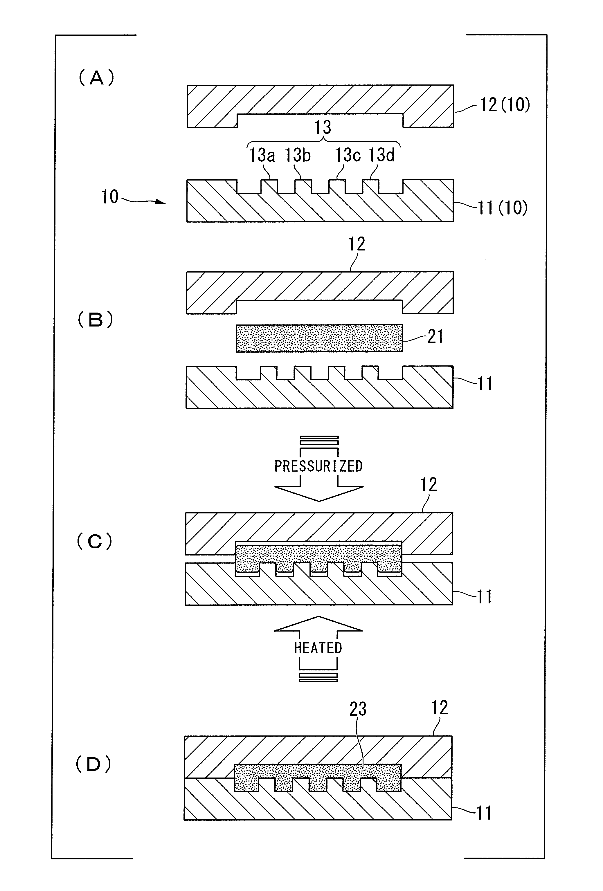
[0137]The fuel cell separator of the embodiment was manufactured as a molded product using a sheet-shaped material including a carbonaceous material as the filler and the sheet press molding method of the invention.

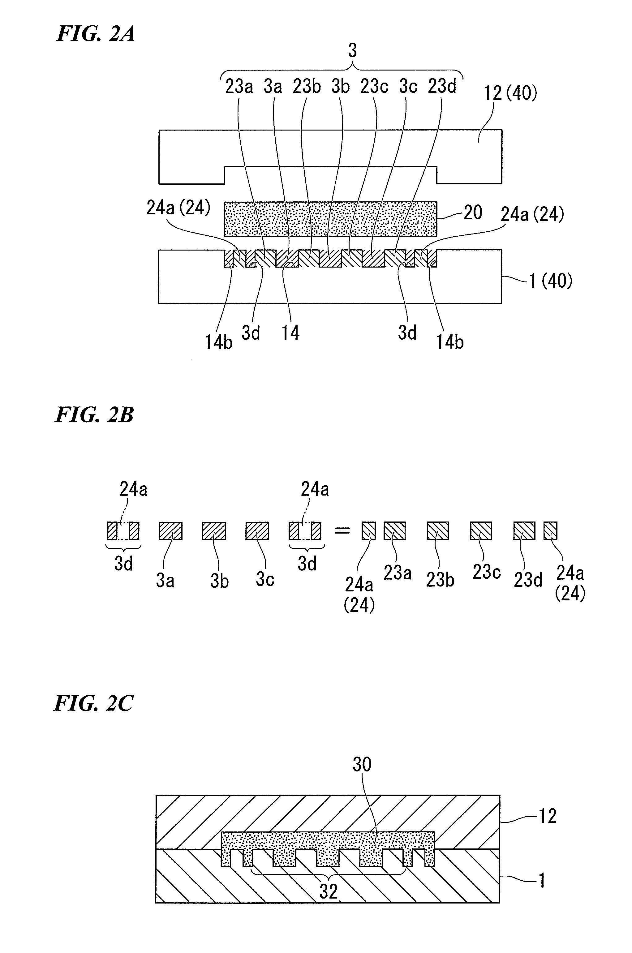
[0138]That is, a fuel cell separator 35 shown in FIG. 3 having a flow channel pattern 31 to which a recess and protrusion pattern is transferred and a plurality of recessed portions 24b, 24c, 24d, and 24e to which a dummy pattern is transferred on one surface is obtained by pressurizing the sheet-shaped material shown below using the pair of molds shown below having the recess and protrusion pattern. FIGS. 3A to 3D are views showing the fuel cell separators of Example and Comparative Example. FIG. 3A is a planar view of the fuel cell separator of Example, FIG. 3B is a cross-sectional view of the cross-section A-A′ in FIG. 3A. In addition, FIG. 3C is a planar view of the fuel cell separator of Comparative Example, and FIG. 3D is a cross-sectional view of the cross-section ...


PUM

PropertyMeasurementUnit
mass ratioaaaaaaaaaa
thicknessaaaaaaaaaa
diameteraaaaaaaaaa

Abstract

Provided is a sheet press molding method by which a molded product having a small plate thickness deviation is obtained. Such a sheet press molding method is provided with a process in which a molded product (30) having a recess and protrusion pattern portion (32), to which a recess and protrusion pattern (3) is transferred, is formed by pressurizing a sheet-shaped material (20) including 60 vol. % to 95 vol. % of a filler and a resin composition using a pair of molds (40) having the predetermined recess and protrusion pattern (3) composed of recessed portions (3a, 3b, and 3c) and protrusion portions (23a, 23b, 23c, and 23d) in at least one of a pair of the molds, in which the mold provided with a dummy pattern (24) composed of dummy protrusion portions (24a) that offset the difference between the total volume of the protrusion portions (23a, 23b, 23c, and 23d) formed on the inside (14) and the total volume of the recessed portions (3a, 3b, and 3c) disposed between the protruding portions (23a, 23b, 23c, and 23d) and the side surfaces (14b) of the inside (14) and the recessed portions (3a, 3b, and 3c) disposed between the protruding portions (23a, 23b, 23c, and 23d) on the inside (14) is used as a pair of the molds (40).

Description

TECHNICAL FIELD[0001]The present invention relates to a sheet press molding method and a method of manufacturing a fuel cell separator. In more detail, the invention relates to a sheet press molding method in which a resin composition sheet containing a filler in a high concentration is used and a method of manufacturing a fuel cell separator in which a resin composition sheet containing a carbonaceous material in a high concentration is used.[0002]Priority is claimed on Japanese Patent Application No. 2009-082279, filed Mar. 30, 2009, the content of which is incorporated herein by reference.BACKGROUND ART[0003]In recent years, a sheet press molding method has been drawing attention as a method of molding thin and large-area products, and has been used for, for example, molding of fuel cell separators. Hereinafter, the sheet press molding method will be described with reference to an example of a method of manufacturing a fuel cell separator.[0004]A fuel cell is a clean power genera...

Claims


Application Information

Patent Timeline
Patent Type & Authority Applications(United States)
IPC IPC(8): B29C59/02
CPCB29C43/021B29C2043/025H01M8/0213Y02E60/50H01M8/0226H01M8/026H01M2008/1095H01M8/0221B29K2105/16B29K2105/256B29L2031/3468Y02P70/50B29C43/02B29C43/36B29C59/02H01M8/02
Inventor UTASHIRO, TOMOYAITO, YOSHINORINOGUCHI, MASAYUKI
Owner SHOWA DENKO KK
Why Eureka
Try Eureka