Method and magnetic resonance apparatus for dynamic phase correction in a multi channel RF transmission

a magnetic resonance and multi-channel technology, applied in the direction of magnetic measurement, geological measurement, reradiation, etc., can solve the problems of phase errors, severe image artifacts, and limitations in the signal readout of the detected mr signal, so as to improve the acquisition speed and minimize phase-induced errors

Active Publication Date: 2012-02-02
SIEMENS HEALTHCARE GMBH
View PDF10 Cites 8 Cited by
  • Summary
  • Abstract
  • Description
  • Claims
  • Application Information

AI Technical Summary

Benefits of technology

[0008]An object of the present invention is to improve the acquisition o

Problems solved by technology

This leads to severe image artifacts in sequences with multiple excitations and/or multiple refocusing pulses for each image in the event that no correction is made.
These sequences, however, impose limitations in the signal readout of the detected MR signal.
The difficulties in fast spin echo sequences (turbo spin echo sequence, TSE, or fast spin echo (FSE), namely in the readout of the signals during a train of 180° refocusing pulses, are particularly significant.
In this case an additio

Method used


Image

  • Method and magnetic resonance apparatus for dynamic phase correction in a multi channel RF transmission
  • Method and magnetic resonance apparatus for dynamic phase correction in a multi channel RF transmission
  • Method and magnetic resonance apparatus for dynamic phase correction in a multi channel RF transmission

Examples


Embodiment Construction

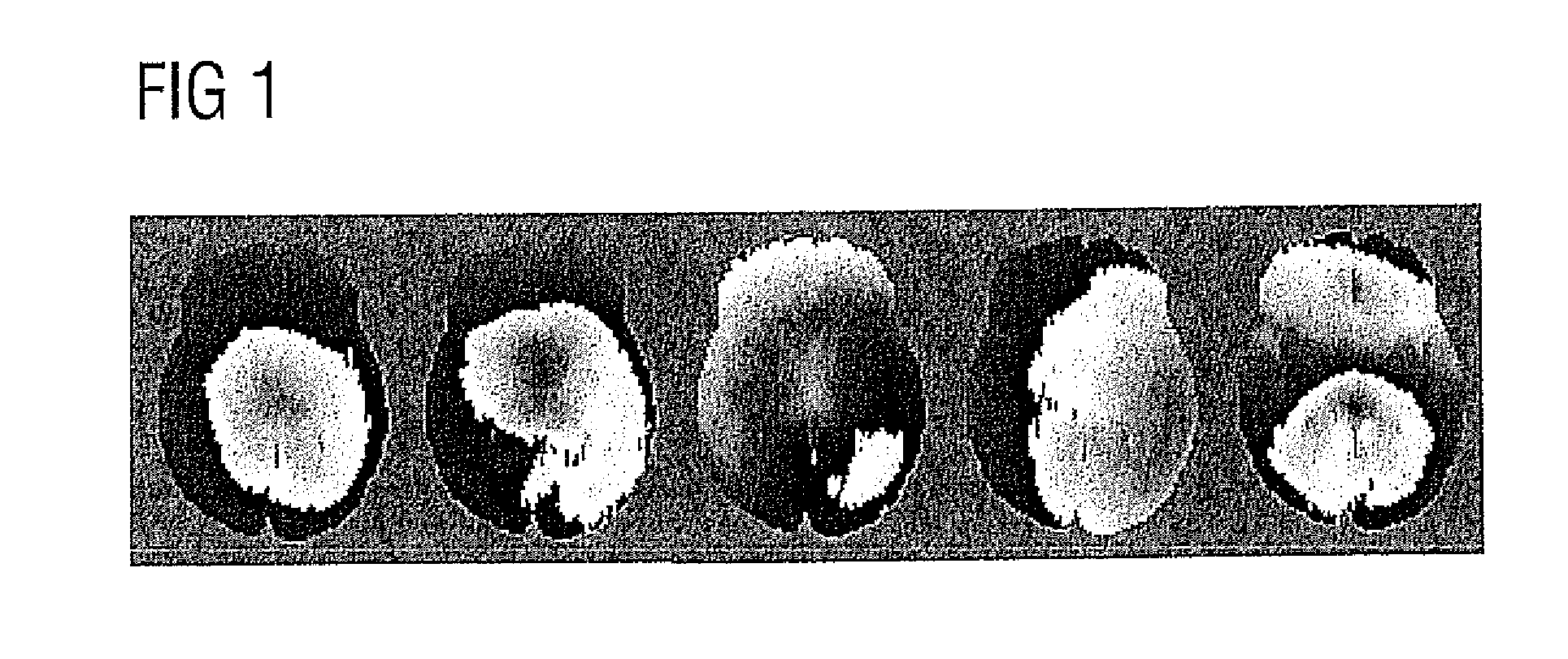
[0023]As is apparent in FIG. 1, the phase variation is rough both between the individually acquired images and respectively in an image. The phase that is shown in greyscale values in the image likewise varies just as in an individual image.

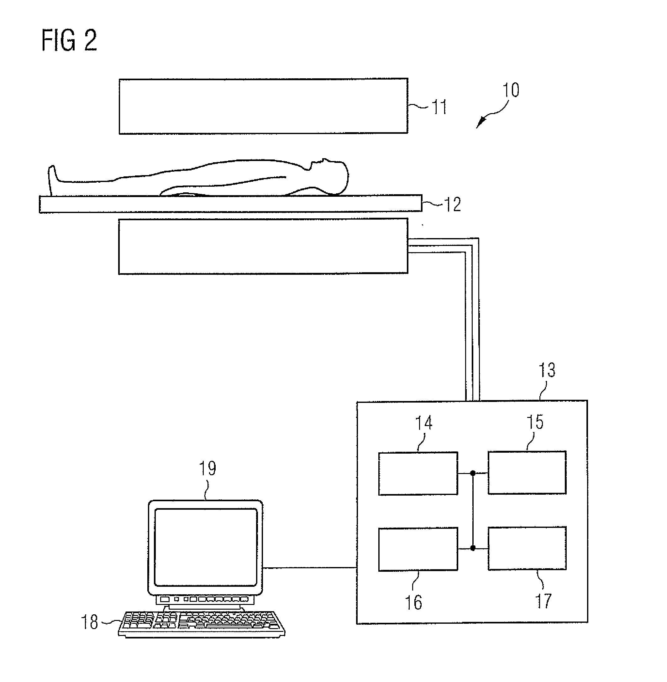
[0024]An MR system with which the method according to the invention can be implemented is shown in FIG. 2. The MR system 10 has a magnet 11 to generate a polarization field B0. An examination subject arranged on a bed 12 is driven into the magnet, and the magnetization resulting in the body is presented with spatial resolution in MR images via radiation of gradients and radio-frequency pulses and the detection of MR signals. How an MR system is designed and how MR images (for example diffusion-weighted MR images) can generally be generated with it is known in general to those skilled in the art and thus need not be described in detail herein. The MR system furthermore has a central control unit 13 with a multichannel RE transmission and reception...


PUM


Abstract

In a method and magnetic resonance (MR) apparatus to acquire spin echo-based MR signals of an examination subject with a multi-spin echo sequence with multiple refocusing pulses after a single excitation pulse in an MR system that has a multichannel RF transmission and reception module: detect a spatial, two-dimensional phase distribution in the examination subject is detected by acquiring navigator signals, a phase and amplitude distribution for the individual transmission channels of the RF transmission and reception module is calculated to generate a magnetic field B1 for one of the RF refocusing pulses to generate the spin echo-based MR signal under consideration of the spatial phase distribution of the navigator signals, and this RF refocusing pulse is radiated via the multichannel RF transmission and reception module with the calculated phase and amplitude distributions of the individual transmission channels.

Description

BACKGROUND OF THE INVENTION[0001]1. Field of the Invention[0002]The present invention concerns a method to acquire spin echo-based magnetic resonance (MR) signals of an examination subject with a multi-spin echo sequence in which multiple refocusing pulses are radiated after each RF excitation pulse, and an MR system for implementing such a method.[0003]2. Description of the Prior Art[0004]Magnetic resonance diffusion-weighted imaging of the brain with multiple echoes per excitation is very sensitive to spatially variant, non-linear phase errors. These errors are caused, among other things, by the pulsing cerebrospinal fluid (CSF) of the brain that occurs upon switching of the diffusion-weighted gradients (Miller K L, Pauly J P. Nonlinear phase correction for navigated diffusion imaging. Magn. Reson. Med. 2003;50:343-353). For example, phase images of a single-shot, diffusion-weighted echoplanar imaging sequence are shown in FIG. 1 herein, wherein it can be seen that the phase curve...

Claims


Application Information

Patent Timeline
IPC IPC(8): G01R33/48G01R33/36
CPCG01R33/4836G01R33/565G01R33/56341G01R33/5617
Inventor PORTER, DAVID ANDREW
Owner SIEMENS HEALTHCARE GMBH
Why Eureka
Try Eureka