Imaging lens and imaging apparatus

a technology which is applied in the field of imaging lens and imaging apparatus, can solve the problems of insufficient wide angle of view to reduce the size of the apparatus, the inability to adjust the symmetry of the optical system, and the inability to achieve excellent correction of various aberrations, so as to improve the symmetry of the optical system, and reduce the size of the optical system

Inactive Publication Date: 2012-02-02
FUJIFILM CORP
View PDF3 Cites 15 Cited by
  • Summary
  • Abstract
  • Description
  • Claims
  • Application Information

AI Technical Summary

Benefits of technology

[0075]It is not necessary that the aperture stop St is located at the position illustrated in FIG. 1. However, it is desirable that the aperture stop St is located in the vicinity of one of the second lens L2, the third lens L3 and the fourth lens L4 to reduce the size of the optical system in the direction of the diameter of the optical system and to improve the symmetricalness of the optical system. Specifically, it is desirable that the aperture stop St is arranged between the second lens L2 and the third lens L3, or between the third lens L3 and the fourth lens L4. It is more desirable that the aperture stop St is arranged between the second lens L2 and the third lens L3.
[0076]When the reduction of the size of the optical system is important, it is desirable that the imaging lens of the present invention is composed of six lenses of the first lens L1 through the sixth lens L6, as described above. However, when an improvement of performance of the optical system is important, more lens or lenses may be used in addition to the six lenses.
[0077]All of surfaces of the lenses in the imaging lens of the present invention may be spherical, as illustrated in FIG. 1. However, when low cost is not so important, the imaging lens of the present invention may include an aspheric surface or surfaces. In that case, the flexibility in design is increased, and higher optical performance is achievable.
[0078]Next, Formulas (1) through (11) and the actions and effects thereof will be described. It is desirable that the imaging lens 1 according to an embodiment of the present invention satisfies the Formulas (1) through (11). In the embodiment of the present invention, one of the Formulas (1) through (11), or an arbitrary combination of Formulas (1) through (11) may be satisfied:
[0079]N1 is the refractive index of the first lens L1 with respect to e-line,
[0080]N2 is the refractive index of the second lens L2 with respect to e-line,

Problems solved by technology

However, for that purpose, the angle of view of the imaging lens needs to be extremely wide.
Therefore, excellent correction of various aberrations, such as curvature of field, chromatic aberrations, and distortion, becomes difficult.
The full angles of view are not sufficiently wide to reduce the sizes of the apparatuses to such an extent requested in recent years.
However, the total length of the optical system is rather long.
Further, since the lens system disclosed in Patent Document 5 uses an aspheric lens, the optical system is cost-disadvantageous, compared with an optical system composed of only spherical lenses.

Method used


Image

  • Imaging lens and imaging apparatus
  • Imaging lens and imaging apparatus
  • Imaging lens and imaging apparatus

Examples


Embodiment Construction

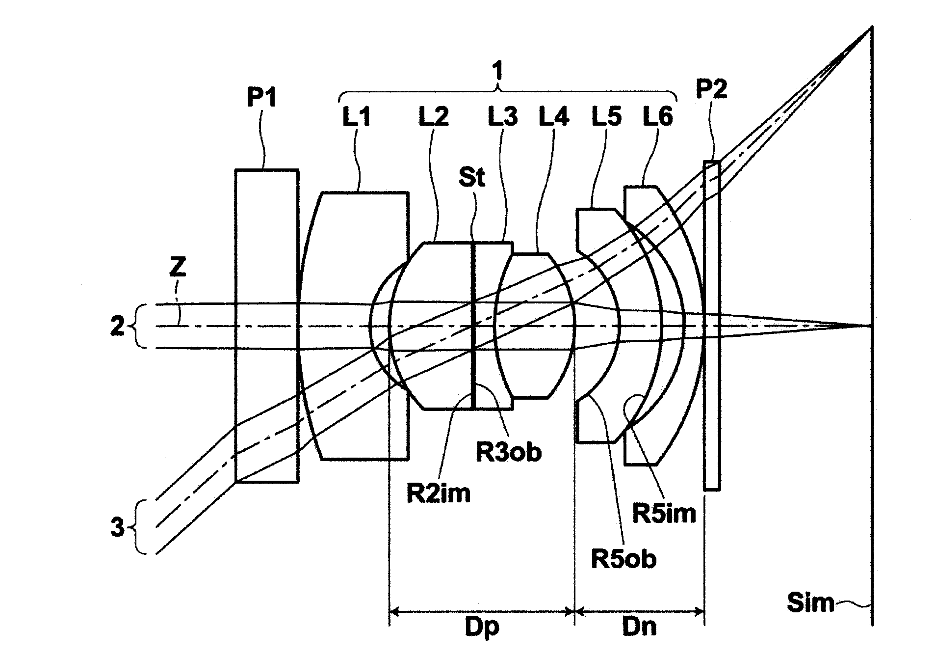
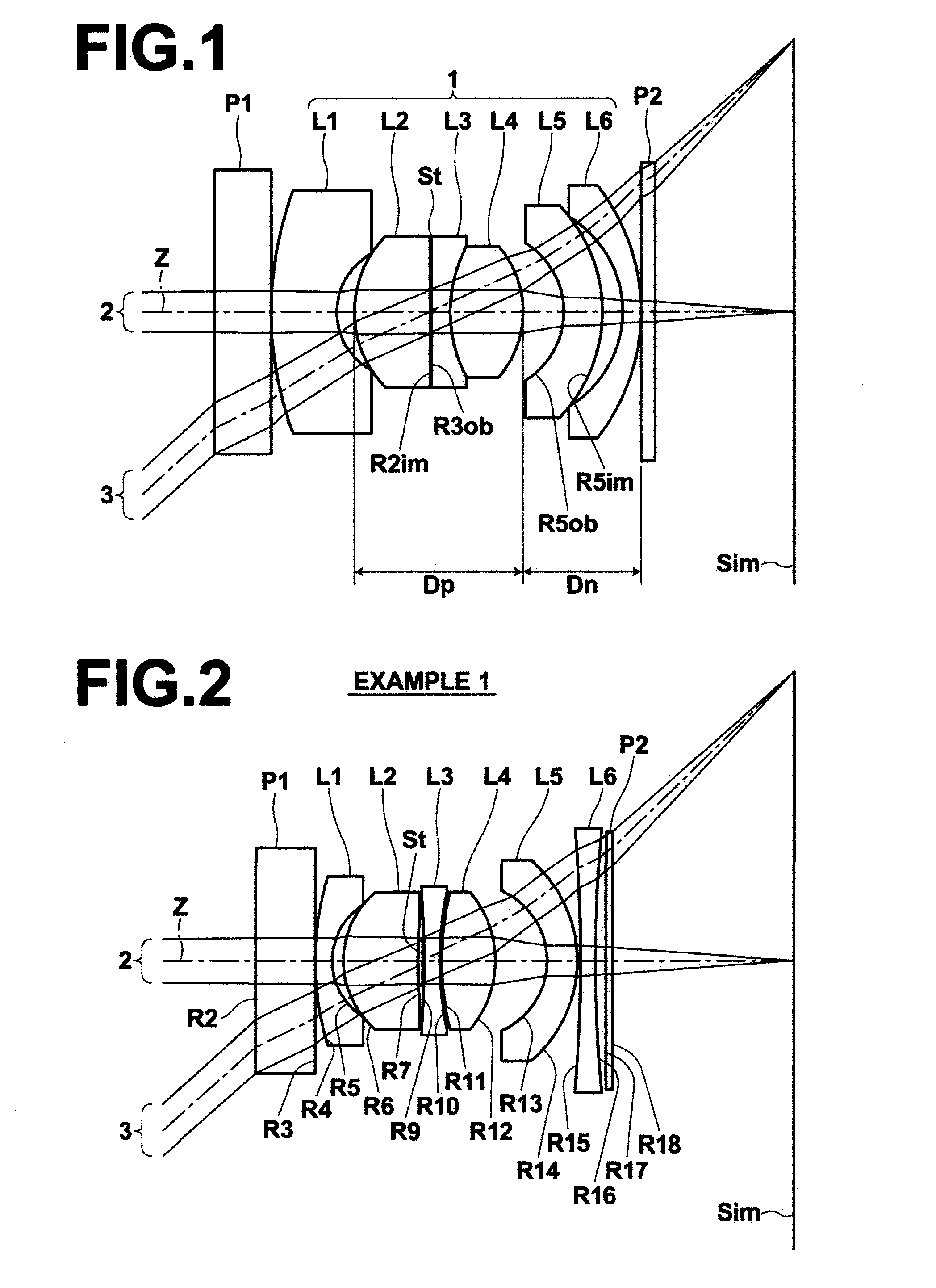
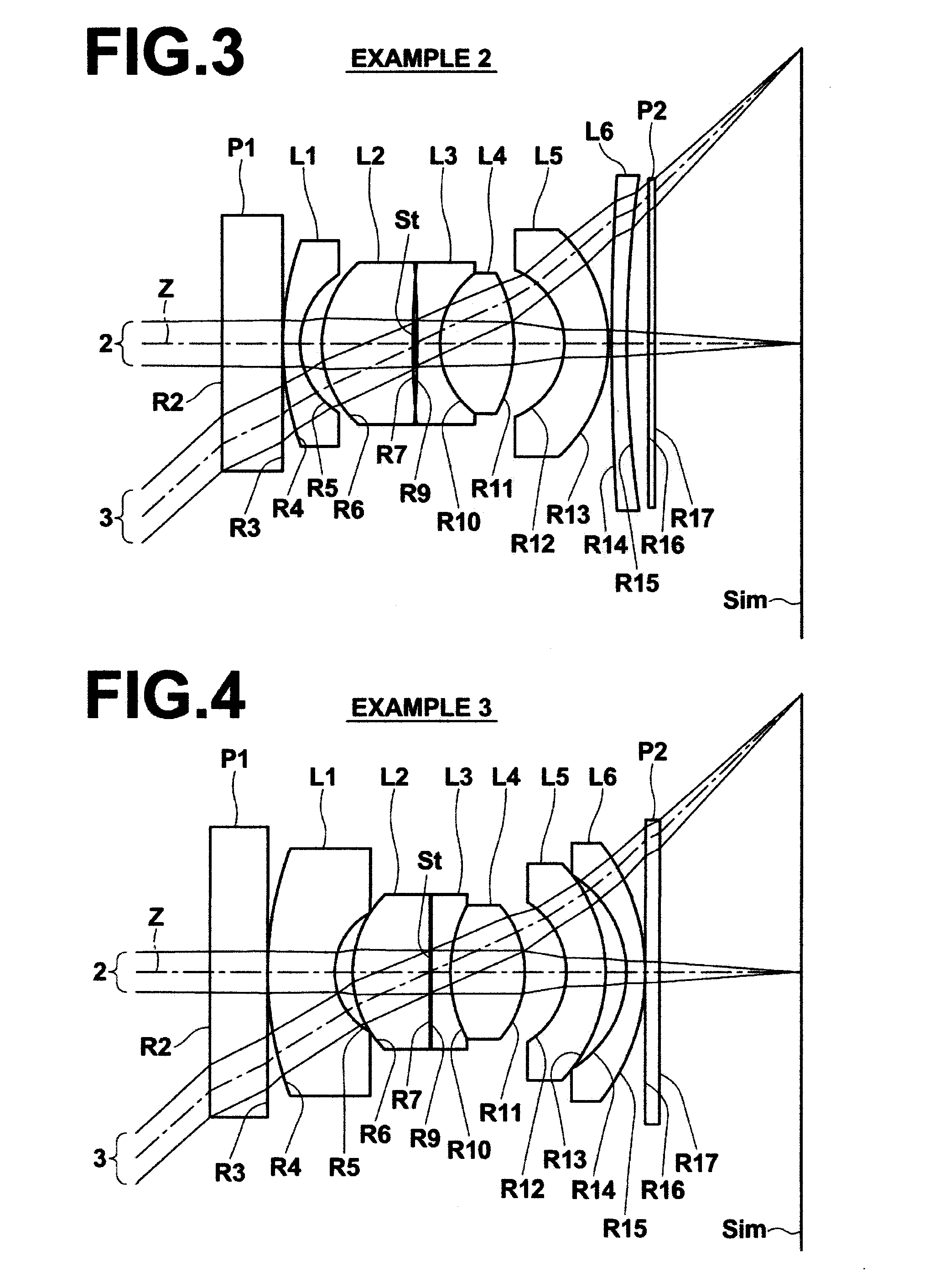
[0060]Hereinafter, embodiments of the present invention will be described with reference to drawings. First, with reference to FIG. 1, an imaging lens according to an embodiment of the present invention will be described. FIG. 1 is a cross section illustrating the structure of an imaging lens 1 according to an embodiment of the present invention and optical paths. The imaging lens 1 illustrated in FIG. 1 corresponds to an imaging lens in Example 3, which will be described later. In FIG. 1, the left side is the object side, and the right side is the image side. Axial rays 2 from an object located at a predetermined finite distance, and rays 3 at a maximum angle of view are also illustrated in FIG. 1.

[0061]As illustrated in FIG. 1, the imaging lens 1 includes first lens L1, second lens L2, third lens L3, fourth lens L4, fifth lens L5, and sixth lens L6, which are arranged along optical axis Z in this order from the object side. The first lens L1 is a negative meniscus lens having a co...


PUM


Abstract

An imaging lens includes a first lens that is a negative meniscus lens having a concave surface facing the image side of the imaging lens, a second lens that is a positive lens having a convex surface facing the object side of the imaging lens, a third lens that is a negative lens having a concave surface facing the image side, a fourth lens that is a double-convex lens, a fifth lens that is a negative meniscus lens having a concave surface facing the object side, and a sixth lens that is a negative lens, which are arranged in this order from the object side.

Description

FIELD OF THE INVENTION[0001]The present invention relates to an imaging lens and an imaging apparatus. In particular, the present invention relates to an imaging lens that is appropriate as a readout lens for reading out an image in an original, and to an imaging apparatus including the imaging lens.DESCRIPTION OF THE RELATED ART[0002]Conventionally, image readout apparatuses were known. The image readout apparatus reads out an image in an original by using a lens, and forms an image on an imaging device, such as a CCD (Charge Coupled Device). Further, image data representing the image are converted into signals. Such image readout apparatuses need to faithfully read out data representing the image in the original. Therefore, various aberrations, such as curvature of field and distortion, need be corrected in an excellent manner in imaging lenses used for readout. Further, as the density of imaging devices became higher in recent years, imaging lenses having higher resolution became...

Claims


Application Information

Patent Timeline
Patent Type & Authority Applications(United States)
IPC IPC(8): G02B9/62
CPCG02B13/005
Inventor MORI, MASAOYAMAKAWA, HIROMITSU
Owner FUJIFILM CORP
Why Eureka
Try Eureka