High-power, phase-locked, laser arrays

a laser array and high-power technology, applied in the field of high-power, phase-locked, laser arrays, can solve the problems of optical gain, most difficult technological challenges, and increase the brightness of a single laser sour

Active Publication Date: 2012-02-02
NECSEL INTPROP
View PDF5 Cites 4 Cited by
  • Summary
  • Abstract
  • Description
  • Claims
  • Application Information

AI Technical Summary

Benefits of technology

[0018]The GHL approach offers a clear and simple path to further power scaling due to its inherent compactness and narrow-band operation. There are two possible routes for GHL power scaling: 1) using GHL as a seed for a larger array of coherent lasers; and 2) using spectral combining of the output of individual GHLs. The first approach, although fea

Problems solved by technology

There are, however, real barriers to increasing the brightness of a single laser source of any design that currently present some of the most difficult technological challenges.
Semiconductor lasers provide the highest electrical-to-optical power-conversion efficiency, and achieve very high optical gain, but typically do not provide sufficiently high contiguous gain volume.
Such ensembles of individual laser emitters, however, cannot readily provide

Method used


Image

  • High-power, phase-locked, laser arrays
  • High-power, phase-locked, laser arrays
  • High-power, phase-locked, laser arrays

Examples


Embodiment Construction

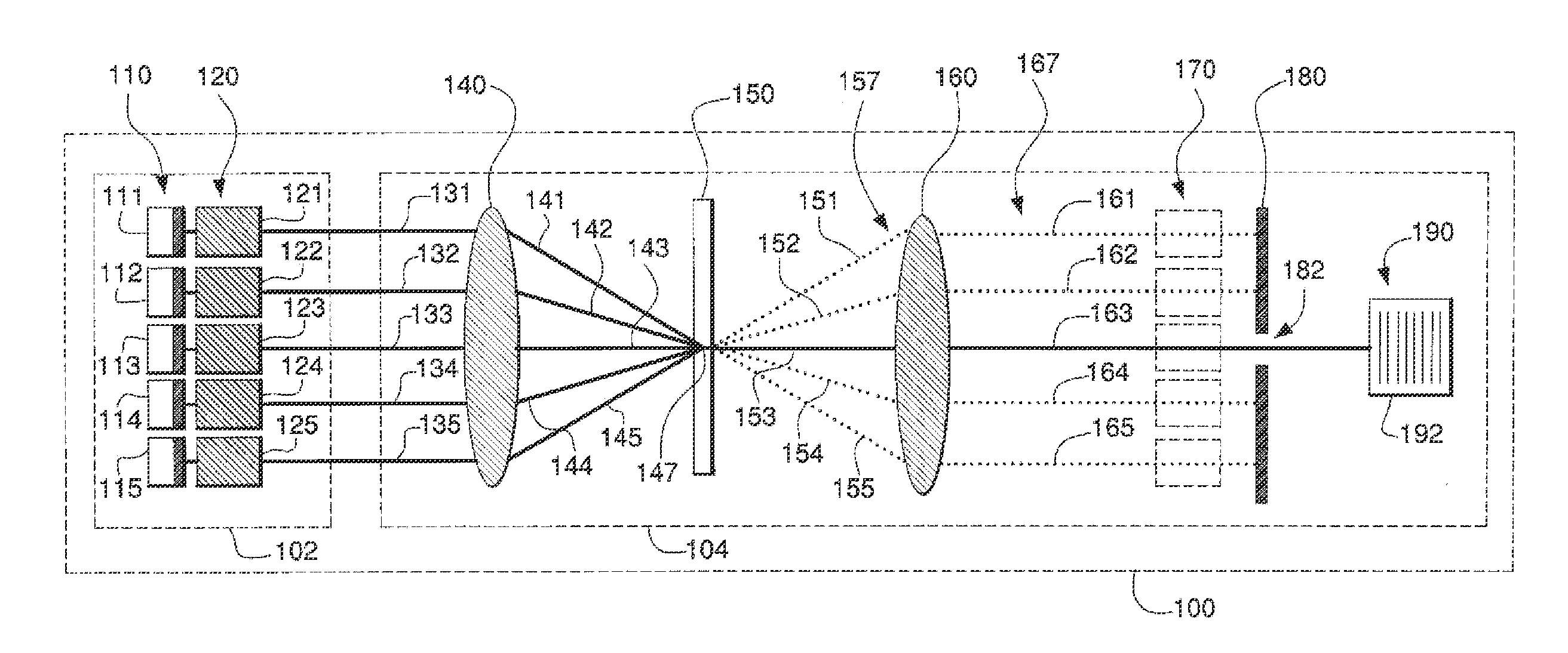
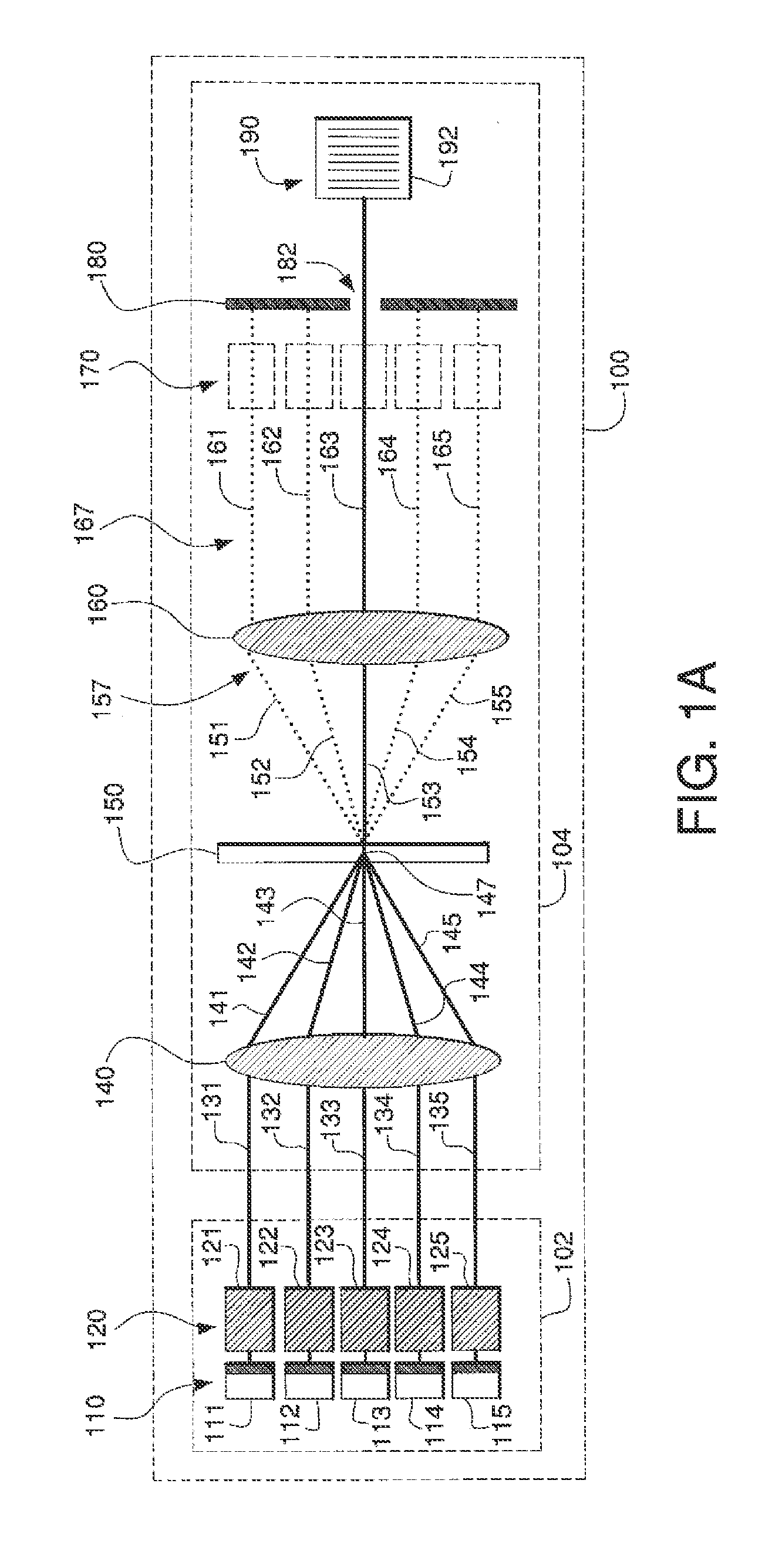
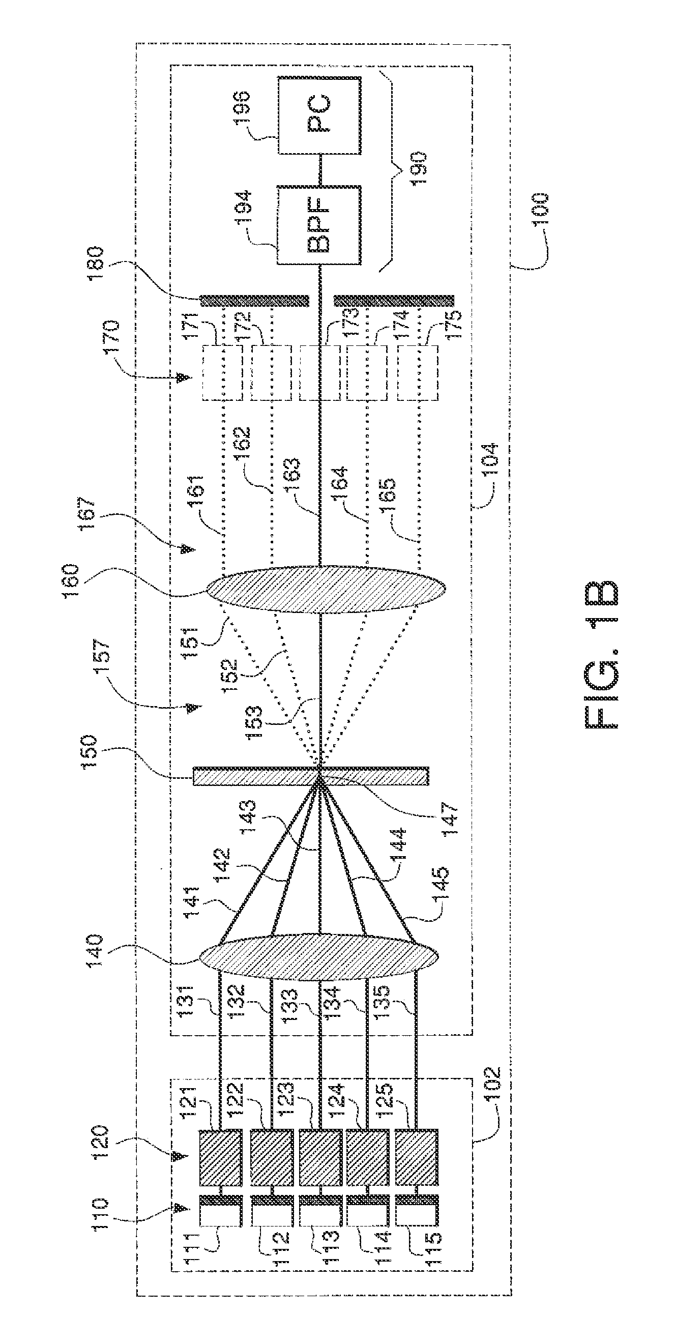
[0025]FIGS. 1A and 1B depict example embodiments of systems and methods for achieving phase synchronization of multiple gain paths of a complex laser cavity. A composite resonator 100, as shown, may include an internal part 102, which may include those components that a typical laser cavity would have, and an external part 104, which may include additional components that enable phase synchronization of multiple gain paths in the laser cavity. The internal part 102 may include an array 120 of gain section resonators 121-125. Each gain section 121-125 may emit light, such as laser light, for example, along a respective optical path 131-135.

[0026]In order to achieve the best phase-locking (i.e., coherence) between the several gain sections 121-125, it may be desirable that coupling, preferably equally-strong coupling, is achieved between each emitter 121-125 in the array 120 and every other emitter 121-125 in the array 120. In order to construct a complete laser cavity with the indepe...


PUM


Abstract

High-power, phased-locked, laser arrays as disclosed herein utilize a system of optical elements that may be external to the laser oscillator array. Such an external optical system may achieve mutually coherent operation of all the emitters in a laser array, and coherent combination of the output of all the lasers in the array into a single beam. Such an “external gain harness” system may include: an optical lens/mirror system that mixes the output of all the emitters in the array; a holographic optical element that combines the output of all the lasers in the array, and an output coupler that selects a single path for the combined output and also selects a common operating frequency for all the coupled gain regions.

Description

CROSS-REFERENCE TO RELATED APPLICATIONS[0001]This application claims benefit under 35 U.S.C. §119(e) of provisional U.S. patent application No. 60 / 649,489, filed Feb. 3, 2005, the contents of which are incorporated herein by reference.BACKGROUND[0002]Lasers are the brightest and, in many instances, some of the most efficient sources of light available today. Nevertheless, there is a constant need to increase their brightness and total power even further. There are, however, real barriers to increasing the brightness of a single laser source of any design that currently present some of the most difficult technological challenges. One of the best examples is semiconductor lasers. Semiconductor lasers provide the highest electrical-to-optical power-conversion efficiency, and achieve very high optical gain, but typically do not provide sufficiently high contiguous gain volume. As a result, optical power in excess of 10 W (i.e., continuous wave) can currently be extracted only from array...

Claims


Application Information

Patent Timeline
IPC IPC(8): H01S3/13G02B27/10
CPCH01S5/005H01S5/065H01S5/0654H01S5/141H01S3/1305H01S5/4012H01S5/4062H01S5/4068H01S5/148
Inventor VOLODIN, BORIS LEONIDOVICH
Owner NECSEL INTPROP
Why Eureka
Try Eureka