
Grain-oriented electrical steel sheet and producing method therefor

a technology of electrical steel and grain orientation, which is applied in the direction of manufacturing tools, furnaces, heat treatment equipment, etc., can solve the problems of increasing the width of the milling, reducing the yield, and difficult to accurately control the application region, so as to achieve the effect of improving yield, reducing the milling width in the post-process and high speed

Inactive Publication Date: 2012-02-02
NIPPON STEEL & SUMITOMO METAL CORP
View PDF2 Cites 10 Cited by
  • Summary
  • Abstract
  • Description
  • Claims
  • Application Information

AI Technical Summary

Benefits of technology

[0062]According to the present invention, during the final annealing, the preferentially-deformable portion which is formed in the lower end portion of the coil is preferentially deformed and the lateral strain developing from the lower end face of the coil is limited by the preferentially-deformable portion, so that the width of the lateral strain portion becomes a substantially constant value. Therefore, the trimming width in a post process may be reduced as much as possible, and thereby the yield is improved.
[0063]In addition, according to the present invention, it is possible to form a preferentially-deformable portion such as a groove and a grain boundary sliding portion at a high speed and with a free pattern using a laser beam. Furthermore, it is possible to perform a working using the laser beam without contacting a steel sheet, such that a problem caused by abrasion (time degradation) in a working device (working tool) such as a roller that is used in a mechanical working does not occur. That is, the amount of working does not vary with the passage of time, such that it is not necessary to replace the working device. Furthermore, it is possible to stably form the preferentially-deformable portion that is optimal for suppressing the lateral strain in a production line of a grain-oriented electrical steel sheet by controlling an irradiation energy density and a beam diameter of the laser beam.

Problems solved by technology

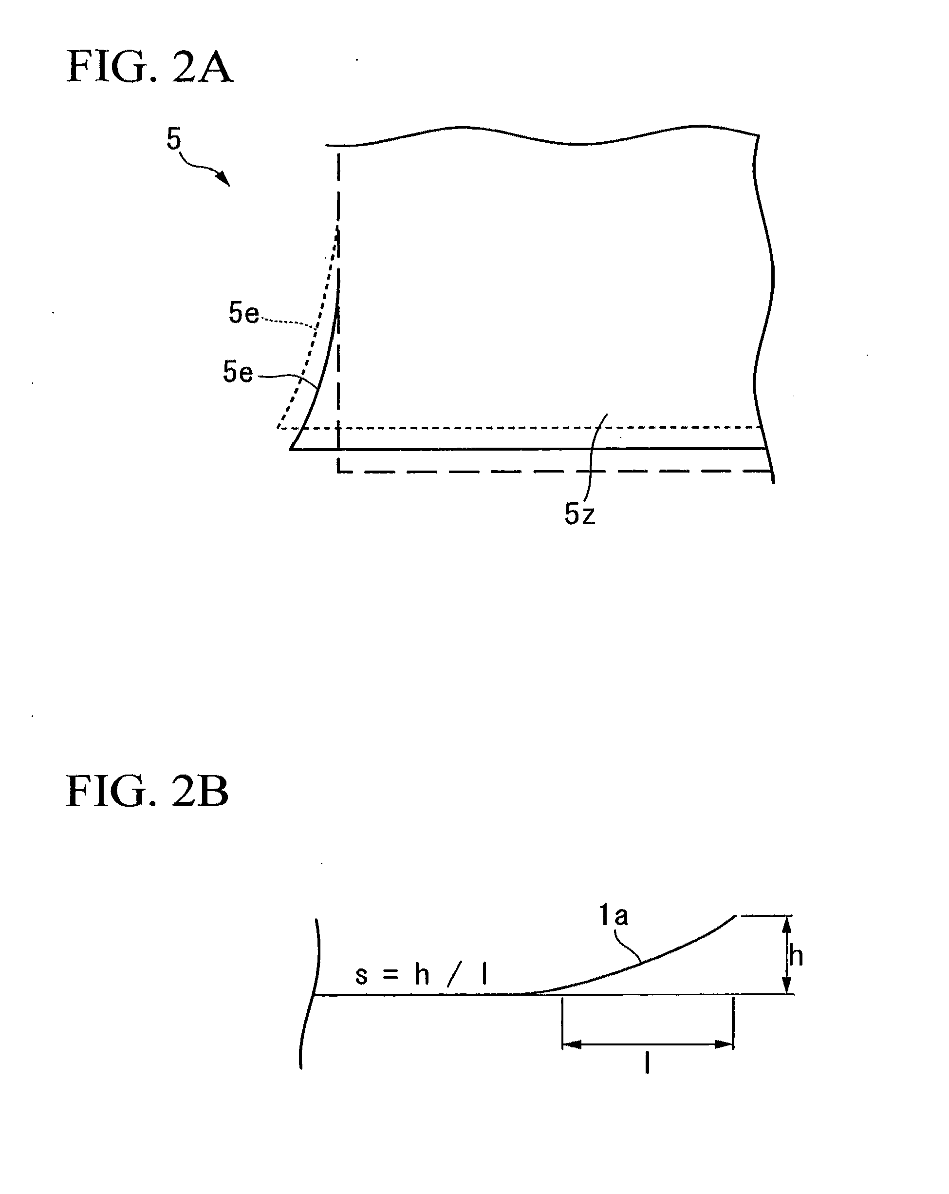
Therefore, as the lateral strain portion 5e increases, the trimming width increases, whereby there is a problem in that the yield decreases.
However, in the method where the grain refiner is applied, which is disclosed in Patent Citation 1, since the grain refiner is in the form of liquid, it is difficult to accurately control the application region.
Therefore, it is difficult to constantly control the width of a grain refining region, such that the width of the lateral strain portion may vary greatly in a longitudinal direction of the coil.
However, there is a problem in that since the roller is abraded due to continuously working over an extended period of time, the amount of strain (reduction ratio) applied diminishes with the passage of time and thereby the grain refining effect decreases.
Particularly, the grain-oriented electrical steel sheet is a hard material containing a large amount of Si, such that the abrasion in the roller is severe, and thereby it is necessary to frequently replace the roller.
However, there is a problem in that in the plasma heating and induction heating, it is difficult to control a heating position and a heating temperature.
In addition, there is a problem in that a region wider than a predetermined range is heated due to heat conduction.
Therefore, it is difficult to constantly control the width of the region where the grain size increases by the secondary recrystallization, such that there is a problem in that non-uniformity may easily occur in the lateral strain suppressing effect.
In the method performed by a mechanical working using the roller or the like, as described above, there is a problem in that the strain application effect (amount of strain) is diminished with the passage of time due to the abrasion of the roller.
Specifically, the rate of the secondary recrystallization varies significantly depending on the amount of strain, such that there is problem in that it is difficult to obtain a predetermined grain size to stably obtain the lateral strain suppressing effect even when the amount of strain due to the abrasion of the roller is small.[Patent Citation 1] Japanese Unexamined Patent Application, First Publication No.
As described above, in the conventional technique, there is problem that since it is difficult to precisely perform the control (range and size) of the crystal grain size, it is difficult to obtain a sufficient lateral strain suppressing effect.

Method used


Image

  • Grain-oriented electrical steel sheet and producing method therefor
  • Grain-oriented electrical steel sheet and producing method therefor
  • Grain-oriented electrical steel sheet and producing method therefor

Examples


example 1

[0130]An example of the first embodiment of the present invention will be described.

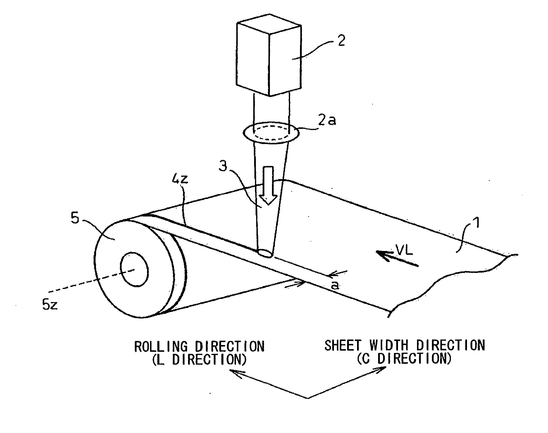
[0131]A CO2 laser was used as the laser device 2 in FIG. 5. A laser power P was controlled to be 1500 W by an electrical input and a condensing shape of the laser was a circular shape with 0.2 mmφ. A steel sheet (grain-oriented electrical steel sheet) 1 with a width of 1000 mm and a thickness t of 0.23 mm after decarburization annealing was fed at a velocity VL of 1000 mm / s in the L direction.

[0132]A distance a, which is a laser beam irradiation position, was spaced by 20 mm from an end face of the steel sheet, a surface in one side of the steel sheet was irradiated with a laser beam over the entire length of the coil (entire length in the L direction), and thereby a groove was formed. As assist gas, dried air under a pressure of 0.5 MPa was used. The cross-sectional shape of the formed groove portion had dimensions: a width W of substantially 0.2 mm and a depth d of substantially 0.02 mm. In this ca...

example 2

[0135]An example of the second embodiment of the present invention will be described.

[0136]A semiconductor laser was used as the laser device 2 of FIG. 7. In the semiconductor laser device, a laser power P could be changed up to 2 kW. In addition, the laser power P could be arbitrarily set using a laser power control device (not shown).

[0137]The laser power P was set to 1000 W, and a condensing shape was set to an elliptical shape where dc was 1.2 mm, and dL was 12 mm. A steel sheet 1 after decarburization annealing, which had a width of 1000 mm and a thickness t of 0.23 mm, was fed in the L direction at a velocity VL of 400 mm / s.

[0138]The distance a from the end face of the steel sheet, which is the irradiation position of the laser beam, was set to 20 mm, and a surface in one side of the steel sheet was irradiated with the laser beam over the entire length (the entire length in the L direction) of the coil. In this case, the energy density Ed of the laser beam was 2.7 J / mm2.

[0139]...

example 3

[0145]Next, the inventors investigated a preferred range of the energy density Ed of the laser irradiation in the second embodiment. That is, the inventors investigated the relationship between the degree of grain refining in the laser irradiation portion and the energy density Ed under a condition where the distance a was 20 mm. Here, the feeding speed VL was set to 1000 mm / s, and the diameter dc of the laser beam in the C direction was set to a constant value of 1.2 mm. The Ed expressed by the above-described Equation (3) was changed by changing the laser power P within a range of 200 to 5000 W and then investigated a crystal state (metallographic structure) of the steel sheet after the secondary recrystallization.

[0146]As a result, when the energy density Ed was 0.5 J / mm2 or more, it was possible to generate a predetermined crystalline structure (linear grain boundary) at the time of the final annealing. However, when the energy density Ed was less than 0.5 J / mm2, it was difficul...


PUM

PropertyMeasurementUnit
Widthaaaaaaaaaa
Widthaaaaaaaaaa
Distanceaaaaaaaaaa

Abstract

A producing method of a grain-oriented electrical steel sheet includes forming a preferentially-deformable portion at an end region of a steel sheet so as to be parallel with the rolling direction of the steel sheet; coiling the steel sheet; and performing a final annealing to the steel sheet after disposing the steel sheet in a manner such that the end region becomes the lower side of the steel sheet.

Description

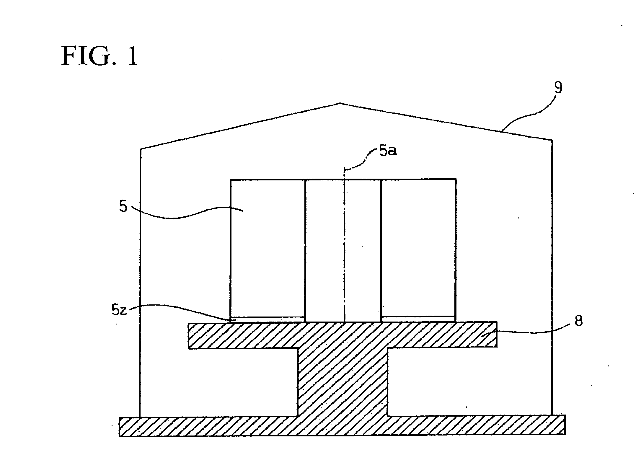
BACKGROUND OF THE INVENTION[0001]1. Field of the Invention[0002]The present invention relates to a method of manufacturing a grain-oriented electrical steel sheet, which prevents lateral strain of a coil end portion brought into contact with a coil receiver in final annealing.[0003]Priority is claimed on Japanese Patent Application No. 2009-058500, filed Mar. 11, 2009, and Japanese Patent Application No. 2009-263216, filed Nov. 18, 2009, the content of which is incorporated herein by reference.[0004]2. Description of Related Art[0005]In a method of manufacturing a grain-oriented electrical steel sheet, a cold-rolled steel sheet is wound in a coil after decarburization annealing, and is subject to a final annealing for the purpose of a secondary recrystallization at high temperatures of 1000° C. or higher. At the time of the final annealing, as shown in FIG. 1, a coil 5 is disposed on a coil receiver 8 in an annealing furnace cover 9 in a manner such that the coil axis 5a of the coil...

Claims


Application Information

Patent Timeline
IPC IPC(8): B32B3/30B21D35/00B32B15/18
CPCC21D1/34C21D8/12C21D8/1272C21D8/1294C21D9/46Y10T428/1234C21D9/663C21D10/005C21D2201/05H01F1/16C21D9/54
Inventor SAKAI, TATSUHIKOATAKE, MAKOTOHAYASHI, SHINYA
Owner NIPPON STEEL & SUMITOMO METAL CORP
Learn More