Porous substrates filled with nanomaterials

Active Publication Date: 2012-02-02
LAWRENCE LIVERMORE NAT SECURITY LLC
View PDF3 Cites 35 Cited by
  • Summary
  • Abstract
  • Description
  • Claims
  • Application Information

AI Technical Summary

Benefits of technology

[0042]In one embodiment, the deposition of the nanomaterial increases the bulk electric conductivity of the porous substrate by 50% or more.
[0043]In one embodiment, the deposition of the nanomateri

Problems solved by technology

In these materials, however, the CNTs are embedded within the skeletal network of the CA

Method used


Image

  • Porous substrates filled with nanomaterials
  • Porous substrates filled with nanomaterials
  • Porous substrates filled with nanomaterials

Examples


Example

Working Examples

[0113]Additional embodiments are also provided in the following non-limiting working examples. For example, ACA-CNT composites were prepared and characterized.

1. Porous Substrate

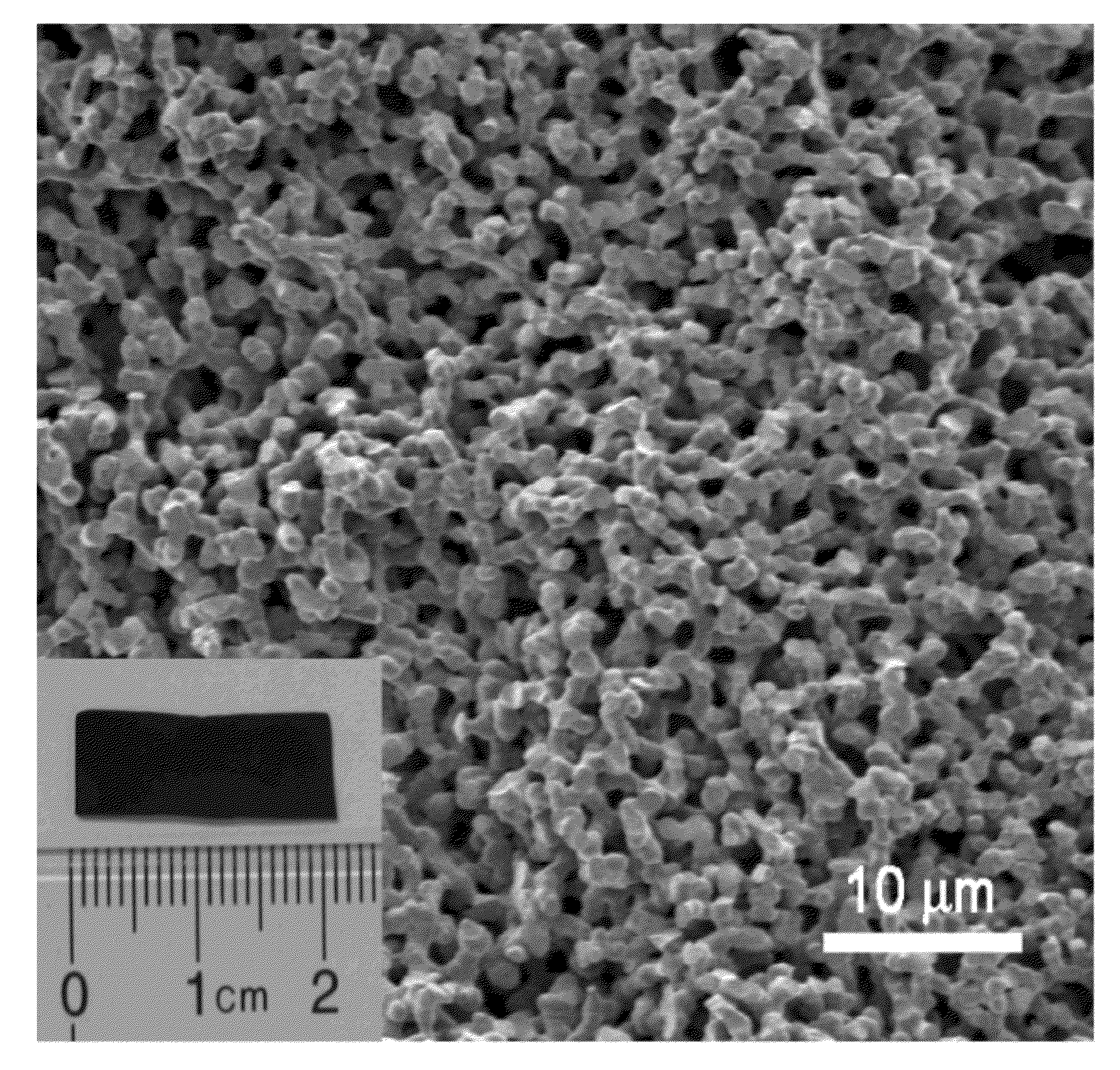
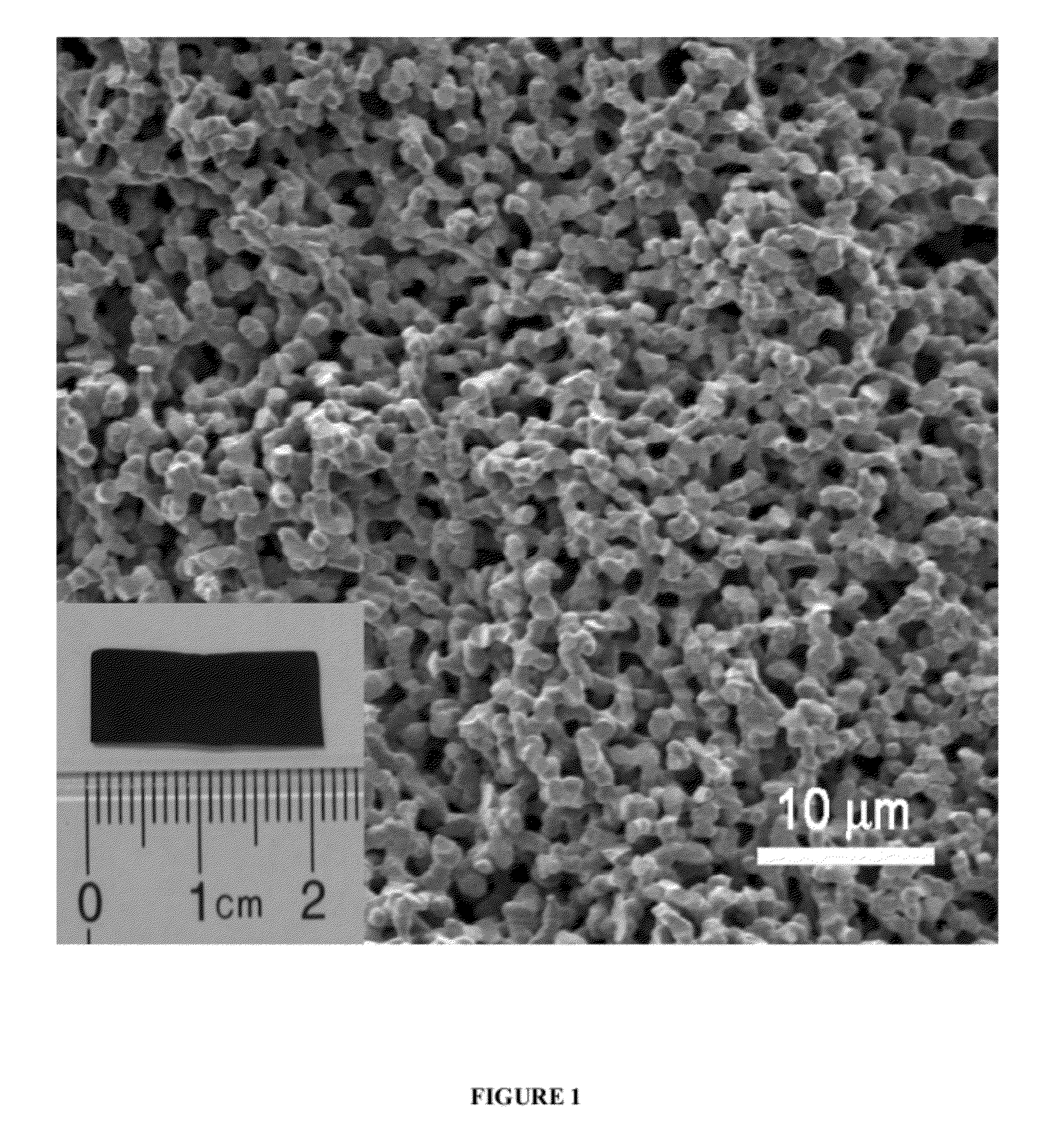
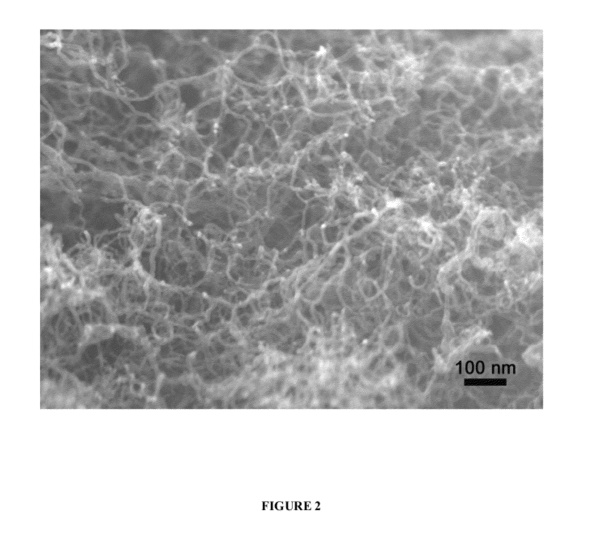
[0114]Activated CAs (ACAs) with large surface areas (over 2000 m2 / g) and bimodal porosity (macro- and micropores) were utilized as CVD substrates. Relative to mesoporous CAs, these macroporous substrates provided enhanced diffusion efficiency of the CVD synthesis gas throughout the aerogel structure and substantially more surface area for deposition of catalyst particles and growth of CNTs. The ACAs were prepared through carbonization and thermal activation of organic aerogels derived from resorcinol and formaldehyde, as previously described.[5] The skeletal structure of the ACA substrate comprises interconnected micron-sized carbon ligaments that define the continuous macroporous network (FIG. 1). The ligaments were porous as well, as the activation process creates micropores and small mesop...


PUM

PropertyMeasurementUnit
Fractionaaaaaaaaaa
Fractionaaaaaaaaaa
Pore sizeaaaaaaaaaa

Abstract

A composition comprising: at least one porous carbon monolith, such as a carbon aerogel, comprising internal pores, and at least one nanomaterial, such as carbon nanotubes, disposed uniformly throughout the internal pores. The nanomaterial can be disposed in the middle of the monolith. In addition, a method for making a monolithic solid with both high surface area and good bulk electrical conductivity is provided. A porous substrate having a thickness of 100 microns or more and comprising macropores throughout its thickness is prepared. At least one catalyst is deposited inside the porous substrate. Subsequently, chemical vapor deposition is used to uniformly deposit a nanomaterial in the macropores throughout the thickness of the porous substrate. Applications include electrical energy storage, such as batteries and capacitors, and hydrogen storage.

Description

RELATED APPLICATIONS[0001]This application claims priority to U.S. provisional applications U.S. Ser. Nos. 61 / 369,972 filed Aug. 2, 2010; 61 / 473,537 filed Apr. 8, 2011; and 61 / 473,654 filed Apr. 8, 2011, which are each incorporated herein by reference in their entireties for all purposes.FEDERAL FUNDING STATEMENT[0002]The United States Government has rights in this invention pursuant to Contract No. DE-AC52-07NA27344 between the United States Department of Energy and Lawrence Livermore National Security, LLC for the operation of Lawrence Livermore National Laboratory.BACKGROUND[0003]A need exists to prepare better composite materials including nanostructured composite materials. For example, many energy applications such as capacitors and batteries require better performance of materials. Nanostructured materials provide the ability to engineer important properties such as surface area and electrical charge transport.[0004]An important class of material is highly porous material whi...

Claims


Application Information

Patent Timeline
IPC IPC(8): H01B1/04B01J32/00C23C16/44B01J21/18C23C16/26B82Y30/00B82Y40/00
CPCB01J21/18B01J21/185B01J23/755B01J35/1028B01J37/0201B82Y30/00H01B1/04C01B31/00C01B31/02C01B31/0233C01B33/02C01B33/027C01B2202/06B82Y40/00C01B32/00C01B32/05C01B32/162
Inventor WORSLEY, MARCUS A.BAUMANN, THEODORE F.SATCHER, JR., JOE H.STADERMANN, MICHAEL
Owner LAWRENCE LIVERMORE NAT SECURITY LLC
Why Eureka
Try Eureka