
Stainless steel for oil well, stainless steel pipe for oil well, and method of manufacturing stainless steel for oil well

a technology of stainless steel and oil well, which is applied in the direction of manufacturing tools, furnaces, heat treatment equipment, etc., can solve the problems that the stainless steel disclosed in patent documents 1 to 3 may not meet the above-described requirements, the cracking of stress corrosion may occur in a high-temperature environment, and the cracking may occur in high-temperature environments, etc., to achieve the effect of improving scc resistance in high-temperature environments, preventing cracking, and preventing crack

Active Publication Date: 2012-02-09
NIPPON STEEL CORP
View PDF2 Cites 23 Cited by
  • Summary
  • Abstract
  • Description
  • Claims
  • Application Information

AI Technical Summary

Benefits of technology

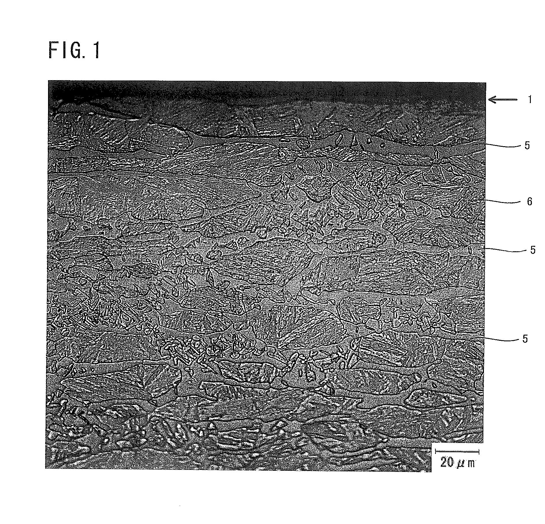
The present invention provides a stainless steel for oil well with high strength, excellent corrosion resistance in high-temperature environments, and good resistance to stress corrosion cracking at normal temperature. The stainless steel has a high Cr content and a specific micro-structure containing a martensitic phase and a ferritic phase. The ferritic phase distribution ratio should be higher than 85%, and the amount of copper should be 1.5 to 3.0% by mass percent. These features improve the performance of the stainless steel in high-temperature environments.

Problems solved by technology

Unfortunately, in the stainless steel pipes disclosed in Patent Documents 1 to 3, cracking may occur when a stress is applied in a high-temperature environment.
That is, stress corrosion cracking may occur in a high-temperature environment.
Therefore, the stainless steels disclosed in Patent Documents 1 to 3 may not meet the above-described requirements (1) to (3).

Method used


Image

  • Stainless steel for oil well, stainless steel pipe for oil well, and method of manufacturing stainless steel for oil well
  • Stainless steel for oil well, stainless steel pipe for oil well, and method of manufacturing stainless steel for oil well
  • Stainless steel for oil well, stainless steel pipe for oil well, and method of manufacturing stainless steel for oil well

Examples


examples

[0080]A steel having the chemical composition given in Table 1 was melted to manufacture a cast piece or a billet.

TABLE 1Chemical compound: unit being mass %, balance being Fe and unavoidable impuritiesValue ofOthersFormula (1)Value ofClassifi-V, Nb, Ti, Zr,Cr + Cu +Formula (2)cationSteelCSiMnPSCrCuNiMoAlNCa, Mg, La, CeNi + MoXInventionA0.0200.240.100.0170.000916.962.485.032.550.0450.0153—27.02−5.88steelB0.0100.250.080.0170.000416.992.424.532.560.0490.0065—26.50−7.03C0.0250.240.170.0180.000517.092.364.512.520.0490.0066—26.48−6.65D0.0270.250.130.0170.000517.492.454.152.530.0450.0110—26.62−7.24E0.0240.250.050.0160.001016.432.454.552.490.0310.0200—25.92−5.49F0.0230.240.180.0190.000516.142.395.472.500.0490.0052—26.50−4.70G0.0200.230.030.0180.000517.042.494.532.540.0410.0069—26.60−6.74H0.0210.250.160.0180.000417.052.394.412.520.0510.0055—26.37−6.85I0.0330.240.150.0180.000417.382.544.942.550.0500.0131—27.41−6.06J0.0220.240.130.0180.000416.862.465.051.800.0500.0080—26.17−5.08K0.0190.240.15...


PUM

PropertyMeasurementUnit
thicknessaaaaaaaaaa
lengthaaaaaaaaaa
temperatureaaaaaaaaaa

Abstract

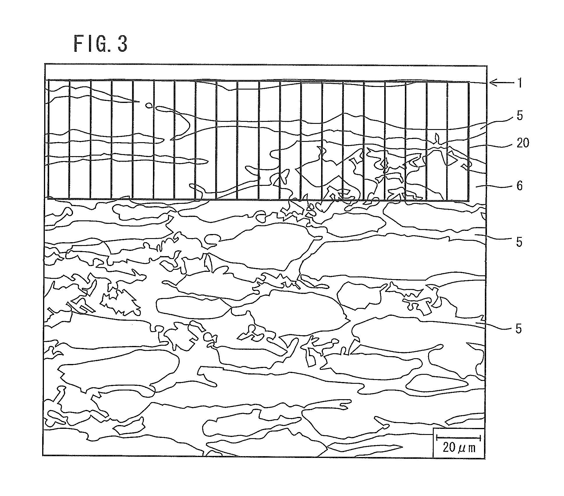
The chemical composition of a stainless steel in accordance with the present invention consists of C: not more than 0.05%, Si: not more than 0.5%, Mn: 0.01 to 0.5%, P: not more than 0.04%, S: not more than 0.01%, Cr: more than 16.0 and not more than 18.0%, Ni: more than 4.0 and not more than 5.6%, Mo: 1.6 to 4.0%, Cu: 1.5 to 3.0%, Al: 0.001 to 0.10%, and N: not more than 0.050%, the balance being Fe and impurities, and satisfies Formulas (1) and (2). Also, the micro-structure thereof contains a martensitic phase and a ferritic phase having a volume ratio of 10 to 40%, and the ferritic phase distribution ratio is higher than 85%.Cr+Cu+Ni+Mo≧25.5  (1)−8≦30(C+N)+0.5Mn+Ni+Cu / 2+8.2−1.1(Cr+Mo)≦−4  (2)

Description

TECHNICAL FIELD[0001]The present invention relates to a stainless steel for oil well and a stainless steel pipe for oil well. More particularly, the present invention relates to a stainless steel for oil well and a stainless steel pipe for oil well, which are used in a high-temperature oil well environment and gas well environment (hereinafter, referred to as “a high-temperature environment”).BACKGROUND ART[0002]Recently, the development of oil wells and gas wells in deep layer has been advanced. (hereinafter, an oil well and a gas well are collectively referred simply to as “an oil well”. Also herein, “a stainless steel for oil well” includes a stainless steel for oil well and a stainless steel for gas well, and “a stainless steel pipe for oil well” includes a stainless steel pipe for oil well and a stainless steel pipe for gas well.) A deep oil well has a high-temperature environment. “A high-temperature environment” contains carbon dioxide gas or carbon dioxide gas and hydrogen s...

Claims


Application Information

Patent Timeline
Patent Type & Authority Applications(United States)
IPC IPC(8): C21D11/00C22C38/44C22C38/50C21D8/00C22C38/48C22C38/42C22C38/46
CPCC21D8/0205C21D8/105C21D9/08C21D2211/005C21D2211/008F16L9/02C22C38/02C22C38/04C22C38/06C22C38/42C22C38/44C22C38/001C21D6/004C21D6/005C21D6/008C21D8/005C21D9/085C22C38/002C22C38/004C22C38/46C22C38/48C22C38/50
Inventor TAKABE, HIDEKIKONDO, KUNIOAMAYA, HISASHIOHE, TAROOTOME, YOHEI
Owner NIPPON STEEL CORP
Learn More