Planar slider test socket

a slider and test socket technology, applied in the field of flying-capable clamp assemblies, can solve the problems of static deformation of the pitch and roll, inability to increase the length of the spring structure, and limited spring structure, so as to reduce the maximum stress

Inactive Publication Date: 2012-02-09
XYRATEX TECH LTD
View PDF4 Cites 16 Cited by
  • Summary
  • Abstract
  • Description
  • Claims
  • Application Information

AI Technical Summary

Benefits of technology

[0017]Another embodiment is directed to a method of the flexure with a flexible hinge connecting two curved beams. The flexible hinge changes the boundary conditions a the end of the curved beams by allowing a rotational movement of the flexures which in turn reduces the maximum stress compared to a curved beam with the same radius of curvature.

Problems solved by technology

The slider removal / reworking operation causes suspension damage, as well as pitch and roll static deformation.
The length of the spring structure cannot be increased and is limited by the size of the slider structure.
The bellows apply an undesirable out of plane moment tending to pop the slider out of the tongue due to manufacturing tolerances during the plastic forming of the bellows.
The moment can also contribute to generating pitch and roll static torque contributing to load and unload magnetic media damage and slider media contact during the slider testing.
This design presents limitations in increasing the frequency response of the system leading to a reduction in the number of zigzags which in turns limits the stroke of the design.
Minimizing the stress at the beams has lead to designing long tapered beams at the leading and trailing edge of the slider resulting in a substantially large design that adds excessive mass at the suspension end.
This mass increase reduces the frequency response of the head assembly and induces an increase of load / unload contact probability, which in turn causes frequency response deterioration.

Method used


Image

  • Planar slider test socket
  • Planar slider test socket
  • Planar slider test socket

Examples


Embodiment Construction

[0060]The embodiments described herein provide a method and apparatus for testing a slider. It will be apparent to one skilled in the art, that the present invention may be practiced without some or all of these specific details. In other instances, well known process operations have not been described in detail in order not to unnecessarily obscure the present invention.

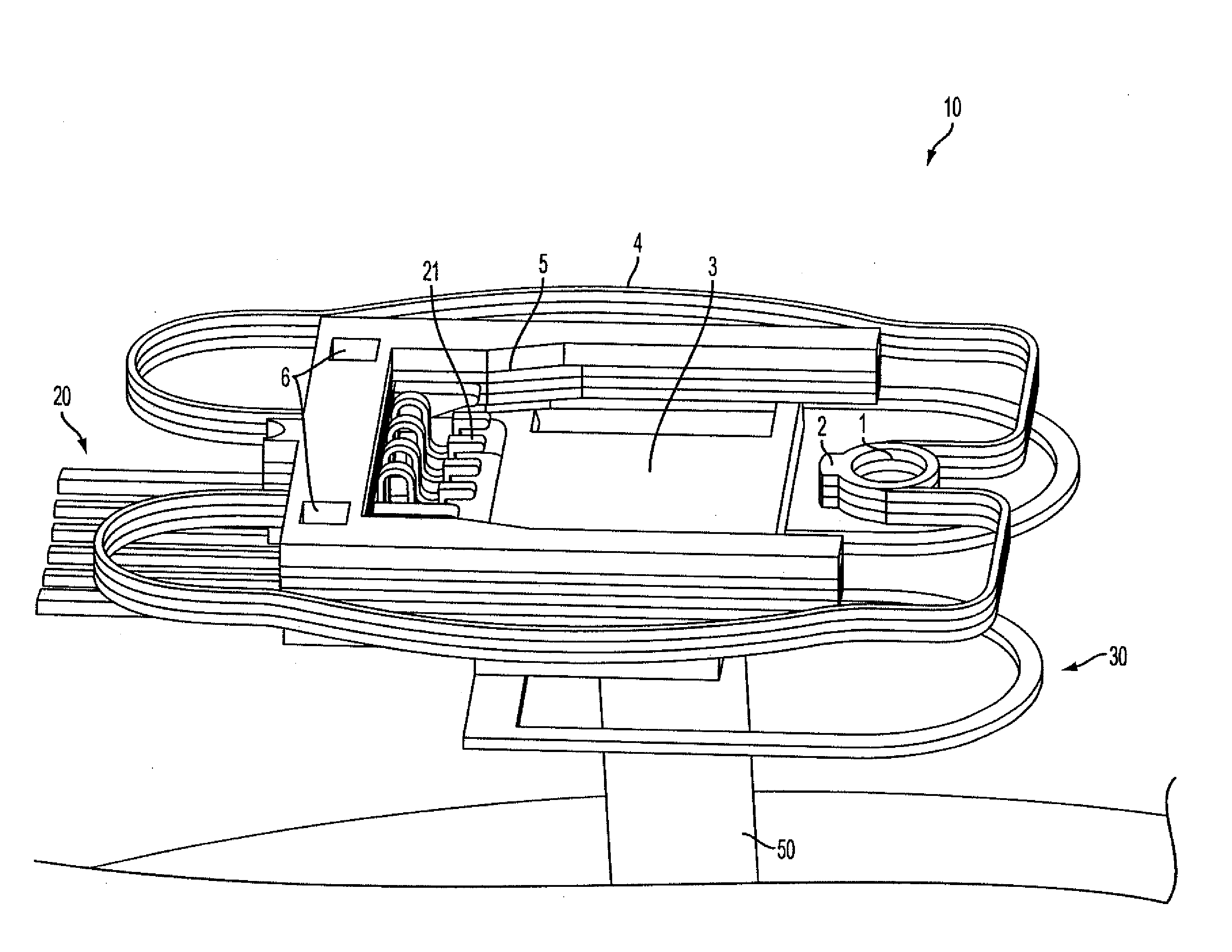
[0061]FIG. 6 illustrates a fly capable slider test socket 100 with various components described in more detail below. A slider test socket 10 is attached to a gimbal structure 30. A center region of the gimbal structure 30 is in turn attached to a preload stem 50, which in turn is connected to a flexible preload spring 40. Flexible preload spring 40 may also be referred to as a flexible preload flexure. Flexible preload spring 40 has a plurality of curvilinear springs extending radially from an inner peripheral surface of an outer circular region of the preload spring to an outer peripheral surface of an inner circu...


PUM

PropertyMeasurementUnit
distanceaaaaaaaaaa
distanceaaaaaaaaaa
distanceaaaaaaaaaa

Abstract

The present application is directed to a slider supporting apparatus for flying a slider of a hard disk drive in the manufacturing process to provide electrical performance characteristics. The present invention discloses an integrated design including the electrical interconnect, the gimballing mechanism, the preload mechanism and the slider supporting mechanism integrated into a single supporting structure.

Description

CLAIM OF PRIORITY[0001]This application is a continuation in part of U.S. application Ser. No. 13 / 206,384 filed Aug. 9, 2011, which is a continuation in part of U.S. application Ser. No. 12 / 938,055 filed Nov, 2, 2010, which claims the benefits of the filing date of U.S. Provisional Patent Application Ser. No. 61 / 363,537 filed Jul. 12, 2010.BACKGROUND[0002]The present application is directed to a fly capable clamp assembly for testing magnetic recording of a substrate, and a method of making and using the same. The present method permits mechanical fly and magnetic testing of magnetic sliders used in the hard disk drive industry. This invention relates to a slider supporting apparatus for flying a slider of a hard disk drive in the manufacturing process to provide electrical performance characteristics.[0003]A disk drive head gimbal assembly (HGA) with a magnetic head is used to write and read data to and from a disk drive. Conventional magnetic heads (also referred to as sliders) ar...

Claims


Application Information

Patent Timeline
Patent Type & Authority Applications(United States)
IPC IPC(8): G11B27/36
CPCG11B5/6011G11B5/455
Inventor BOUTAGHOU, ZINE-EDDINECRANE, PETERGOGLIA, PETER R.
Owner XYRATEX TECH LTD
Why Eureka
Try Eureka