Pipe insulation product with charge dissipater

a technology of dissipation device and pipe insulation, which is applied in the direction of film/foil adhesive, pipe, synthetic resin layered products, etc., can solve the problems of loss of efficiency of cooling unit, increased time and/or expense in operating system, and reduced system efficiency, so as to reduce static charge generation, reduce shipping damage, and dissipate charge

Active Publication Date: 2012-02-16
JOHNS MANVILLE CORP
View PDF0 Cites 1 Cited by
  • Summary
  • Abstract
  • Description
  • Claims
  • Application Information

AI Technical Summary

Benefits of technology

[0011]The laminate may additionally include a closure flap configured to adhesively couple opposite sides of the laminate so that the laminate forms a substantially cylindrical shape with at least a portion of the tubular core enclosed therein; and the laminate may include a charge dissipator applied to the polymeric film sheet layer in an amount sufficient to reduce a static charge on the exterior surface of the laminate without affecting the closure flap's ability to adhesively couple the opposite ends of the laminate. The charge dissipator may provide increased resistance to shipping damage during transportation of the pipe insulation product. The laminate may be flexible so that the tubular core and laminate can be opened, placed about a pipe, and closed without degrading the laminate.
[0012]The charge dissipator may provide increased resistance to shipping damage by reducing friction between the pipe insulation product and one or more surrounding objects during transportation of the pipe insulation product. In addition, the charge dissipator may reduce a static charge by reducing the generation of a static charge on the exterior surface of the laminate.
[0013]According to another embodiment, the present invention may include a method for producing a roughly rectangular laminate jacket for a pipe insulation product. The method may include providing a foil or metallized polymeric sheet material that forms an inner layer of the laminate and that provides a fluid vapor barrier to minimize fluid vapor transmission through the laminate. The method may also include providing a scrim comprising a mesh of a plurality of fibers. The method may further include providing a porous media sheet material. The method may additionally include providing a polymeric sheet material that forms an outer exposed layer of the laminate.
[0014]The method may additionally include bonding the foil or metallized polymeric sheet material, the scrim, the porous media sheet material, and the polymeric sheet material together with an adhesive to form the laminate jacket. The laminate jacket may include a closure flap configured to adhesively couple opposite sides of the laminate jacket so that the laminate jacket forms a hollow cylindrical shape. The method may additionally include applying a charge dissipator to the polymeric film sheet material in an amount sufficient to reduce a static charge on the exterior surface of the laminate jacket without affecting the closure flap's ability to adhesively couple the opposite ends of the laminate jacket. The charge dissipator may provide increased resistance to shipping damage during transportation of the pipe insulation product.
[0015]The method may additionally include positioning a tubular core of insulating material adjacent to the foil or metallized polymeric sheet material and bonding the tubular core of insulating material and the foil or metallized polymeric sheet material with an adhesive to form the pipe insulation product. The pipe insulation product may be flexible so that the tubular core and laminate jacket can be opened, placed about a pipe, and closed without degrading the laminate jacket.
[0018]The porous media layer may include a porous media and a scrim that includes a mesh of a plurality of fibers. The scrim may be an electrically conductive material and may be positioned directly adjacent to the polymeric film sheet layer to dissipate a charge from the laminate's outer surface. In addition, the foil or metallized polymeric film sheet layer may be positioned directly adjacent to the polymeric film sheet layer to dissipate the charge from the laminate's outer surface. A charge dissipator may be applied to the polymeric film sheet layer in an amount sufficient to reduce generation of a static charge on the exterior surface of the laminate. The charge dissipator may provide increased resistance to shipping damage during transportation of the pipe insulation product.

Problems solved by technology

The addition or removal of heat may result in the decreased efficiency of a system and / or increased time and / or expense in operating the system.
For example, in HVAC systems, the addition of heat to cooled fluids may result in loss of efficiency for a cooling unit and may also result in increased expense because of increased operating time and energy needed to achieve a desired cooling level.
The outer surface of the pipe insulation product, however, may be susceptible to damage which may degrade the visual quality of the pipe insulation product and / or piping system in which it is used.
During shipping, the vibrational forces imparted to the individual segments and / or the jostling that occurs between the segments and / or the packaging may result in scuff marks and / or creases forming on the outer surface of the pipe insulation product.
In addition, a static charge may build up on the pipe insulation product's outer surface, which may cause pieces of dust (e.g., fiberglass dust) to accumulate on the pipe insulation product's outer surface and / or cause a static discharge between the outer surface and a surrounding object.
The static discharge may be a source of discomfort for handlers of the pipe insulation product or, in extreme cases, may be the source for a fire.
These visible marks may degrade the overall appearance of the building or structure in which they are used and / or may leave a negative impression on the viewer as to the quality of the pipe insulation product.

Method used


Image

  • Pipe insulation product with charge dissipater
  • Pipe insulation product with charge dissipater
  • Pipe insulation product with charge dissipater

Examples


Embodiment Construction

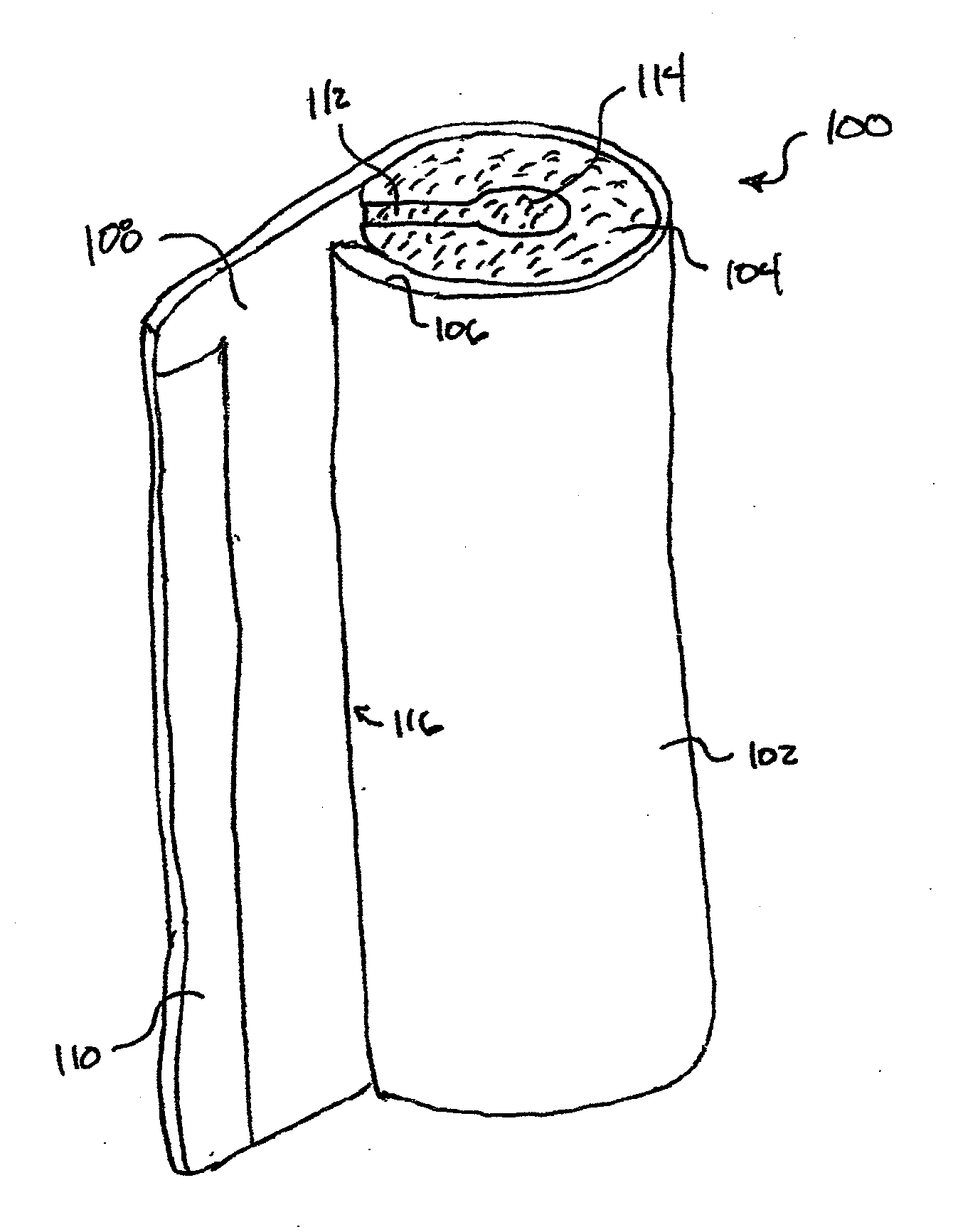
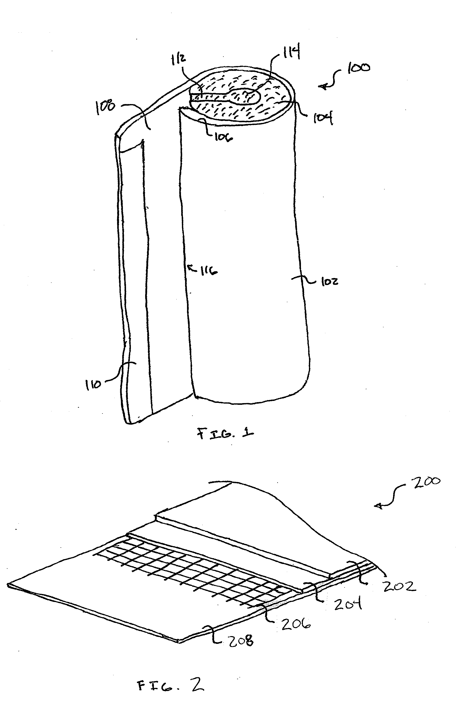
[0026]The present invention includes a pipe insulation product that is used to insulate and / or protect one or more sections of pipe. For example, in addition to minimizing heat transfer between the insulated sections of pipe and the surrounding environment, the pipe insulation product may also shield or protect the pipe from one or more environmental elements (e.g., water vapor). The protection / shielding function minimizes potential risks for the pipe and / or for surrounding objects (e.g., condensation of water vapor on the pipes; mold, mildew, and / or fungal growth; water drip damage; loss of the pipe insulation product's insulating value; etc.).

[0027]The pipe insulation product may also serve an aesthetic purpose when fitted about pipe sections. For example, pipe insulation products are often designed to provide a smooth, finished, and visually appealing outer surface to enhance the visual appeal of the piping systems. The pipe insulation product, however, may be susceptible to one ...


PUM

PropertyMeasurementUnit
lengthaaaaaaaaaa
thicknessaaaaaaaaaa
diameteraaaaaaaaaa

Abstract

A pipe insulation product including a core of insulating material and a roughly rectangular laminate. The core may include an outer surface; an inner surface; and a wall extending between the outer and inner surfaces. The laminate may include a foil or metallized polymeric film sheet layer, a scrim, a porous media sheet layer, and a polymeric film sheet layer bonded together via an adhesive. The polymeric film sheet layer may also include a closure flap that adhesively couples opposite ends of the laminate together to form a cylindrical tube with the core enclosed therein. A charge dissipator may be applied to the polymeric film sheet layer in an amount sufficient to reduce generation of a static charge on the laminate's exterior surface without affecting the closure flap's ability to adhesively couple the opposite ends of the laminate.

Description

CROSS-REFERENCES TO RELATED APPLICATIONS[0001]This application is related to the following Non-Provisional U.S. patent applications: U.S. patent application Ser. No. ______ (attorney Docket No. 7983) filed on Aug. 13, 2010 by Shumate, entitled “Systems and Methods for Insulating a Pipe;” U.S. patent application Ser. No. ______ (attorney Docket No. 7982) filed on Aug. 13, 2010 by Shumate et al., entitled “Insulation Product with Inward Curling Closure Flap;” and U.S. patent application Ser. No. ______ (attorney Docket No. 7984) filed on Aug. 13, 2010 by Shumate et al., entitled “Pipe Insulation Products and Methods.”[0002]The entire disclosures of all of the aforementioned Non-Provisional U.S. patent applications are hereby incorporated by reference, for all purposes, as if fully set forth herein.BACKGROUND OF THE INVENTION[0003]The subject invention relates generally to pipe insulation products and more specifically to pipe insulation products comprising an insulating material core ...

Claims


Application Information

Patent Timeline
Patent Type & Authority Applications(United States)
IPC IPC(8): F16L59/147B32B37/16B32B37/12
CPCB32B5/028B32B2307/3065B32B15/20B32B27/36B32B29/02B32B2255/205B32B2262/101B32B2307/202F16L59/022B32B15/14B32B27/12B32B1/08B32B2038/0092B32B2307/304Y10T428/1359Y10T428/1314B32B37/12B32B37/14B32B2597/00F16L9/14F16L59/14B32B5/024B32B27/10B32B27/30B32B27/304B32B27/32B32B3/26B32B2255/10B32B2262/105B32B2262/108B32B2266/02B32B2266/0228B32B2266/025B32B2266/0278B32B2266/0285B32B2266/04B32B2270/00B32B2307/546B32B2307/714B32B2307/7242B32B2307/7265B32B2307/732F16L59/029F16L59/028B32B7/12
Inventor SHUMATE, MONROE WILLIAMBRISTOL, DEREK COOPER
Owner JOHNS MANVILLE CORP
Why Eureka
Try Eureka