Fluid conditioning arrangements

a technology of flue-condensing and heating arrangements, which is applied in the direction of lighting and heating apparatus, heating types, laminated elements, etc., can solve the problems of system requirements and low time temperature, and achieve the effect of reducing the number of components needed, improving energy usage effectiveness, and increasing the effective volum

Inactive Publication Date: 2012-02-16
VKR HLDG AS
View PDF6 Cites 32 Cited by
  • Summary
  • Abstract
  • Description
  • Claims
  • Application Information

AI Technical Summary

Benefits of technology

[0023]This configuration is particularly advantageous because it allows systems to be built up from a number of modules for variable energy requirement. It may also reverse conventional thinking when it is configured without any driven or powered component in the module. It may thus allow for retrofitting to existing air flow systems. It also improves energy usage effectiveness.
[0024]In a subsidiary aspect, said inlet and / or said outlet incorporates one or more flow regulating valves. If the module consists of these components only it further reduces the number of components necessary and allows for particularly compact modules compared to module incorporating power components per module.
[0025]In a further subsidiary aspect, said PCM packs are arranged substantially side by side. In this configuration, the cooling is advantageous.
[0026]In a further subsidiary aspect, said PCM packs are separated by one or more thermal conductors extending transversely and forming said channels. This allows the PCM portion to be of greater effective volume and therefore improves its effectiveness.
[0027]Further aspects improve one or more of the following: the effectiveness of the PCM, the turbulence of the flow, the compactness of the system relative to its effectiveness, its overall packaging weight and its manufacturing requirements.

Problems solved by technology

Because these cycles rely on natural fluctuations and the weather, on occasion the night time temperatures may not be low enough to freeze or recharge the PCM.
Because the latent heat store is finite there may be occasions where the system is required to provide more energy than stored.

Method used


Image

  • Fluid conditioning arrangements
  • Fluid conditioning arrangements
  • Fluid conditioning arrangements

Examples


Embodiment Construction

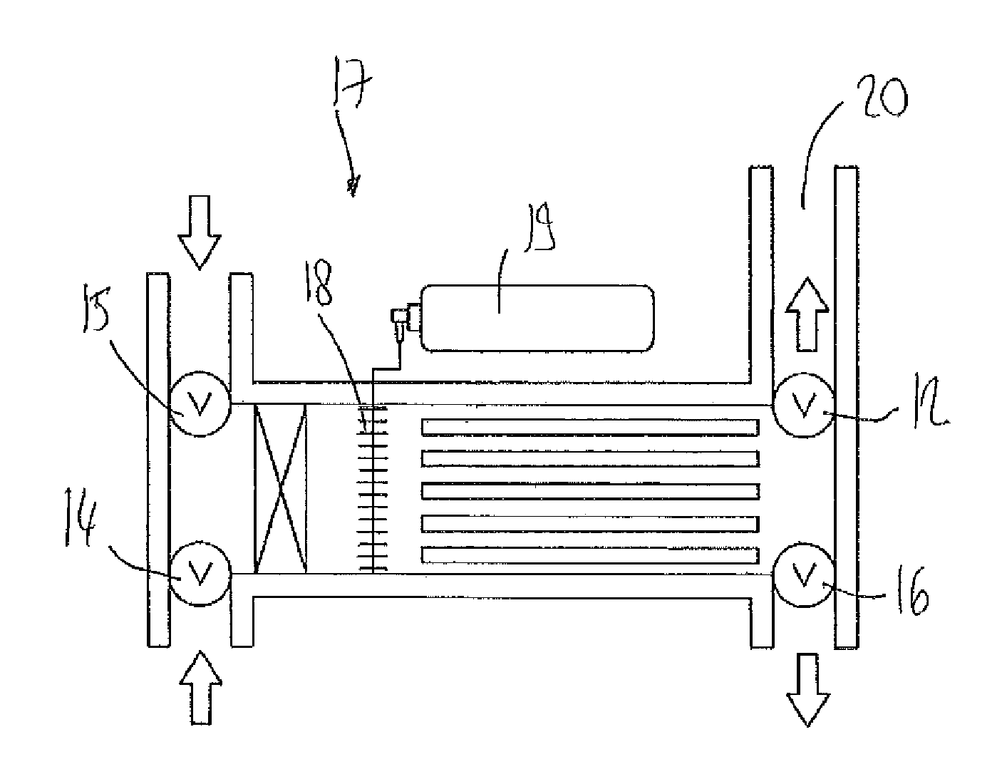
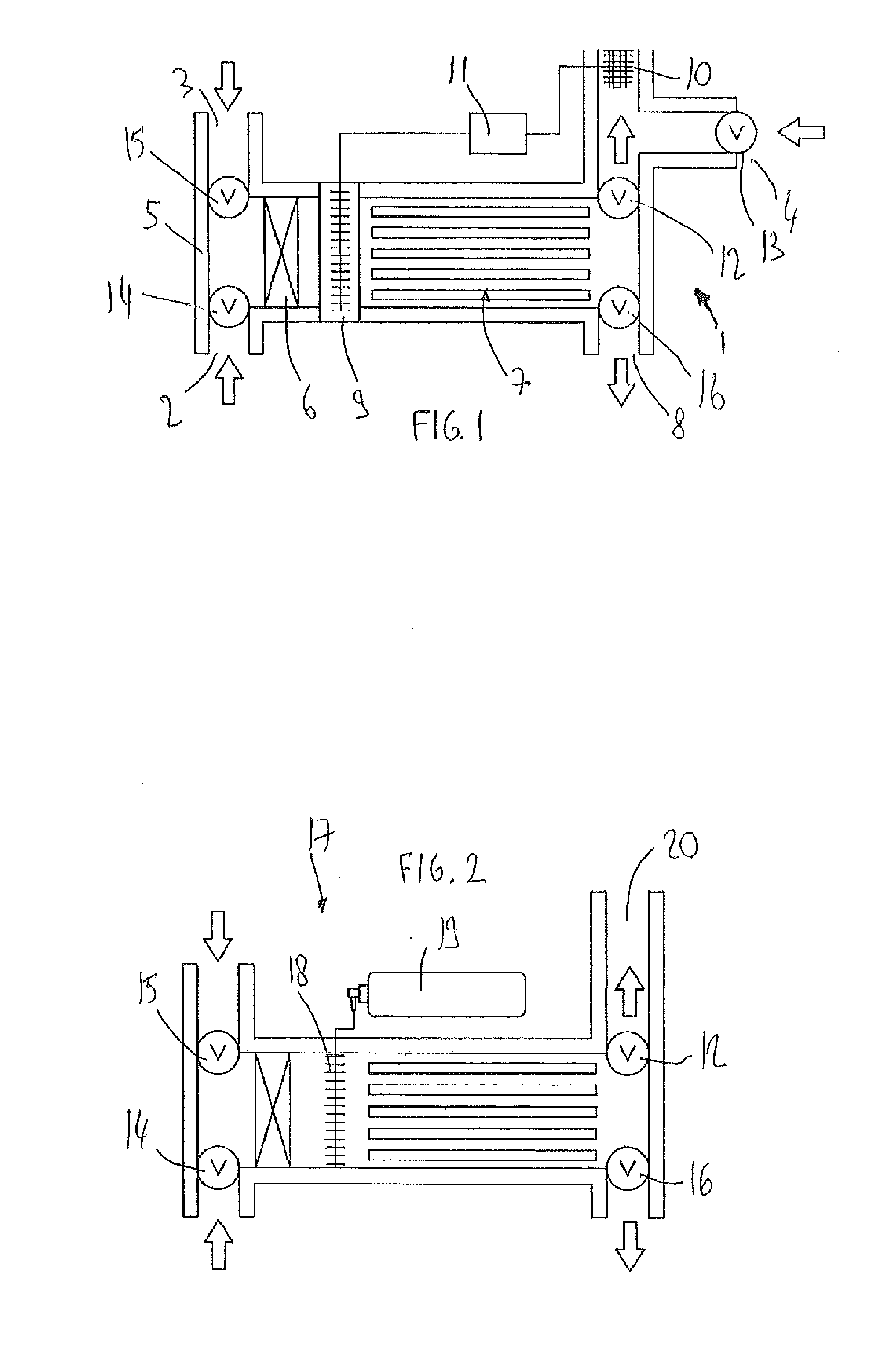
[0101]FIG. 1 shows a fluid conditioning arrangement generally referenced 1. The air conditioning arrangement 1 incorporates three air inlets respectively referenced 2, 3 and 4. Through inlet 3 fresh air from outside is drawn into the housing 5 by a fan or pump 6. It is important to note that whilst the embodiments of the invention are primarily illustrated for cooling air, other fluids may also be cooled and / or heated using these systems. In a conventional mode of operation the air is fed through a PCM heat exchanger 7 so that any heat in the air may be absorbed by the PCM before exiting the housing through outlet 8. The arrangement may preferably be equipped with a controller which may be configured to measure the temperature of the PCM in order to determine the extent of cooling that may be achieved by the heat exchanger. If due to the conditions surrounding the heat exchanger, a booster is required, as for example, the PCM heat exchanger fails to be effective or the incoming flui...


PUM


Abstract

A fluid conditioning arrangement comprises a primary heat exchanger configured to cool and/or heat the fluid; a secondary heat exchanger configured to cool and/or heat the fluid; and a controller for operating said secondary heat exchanger when said primary heat exchanger fails to cool and/or heat the fluid at a predetermined acceptablelevel; wherein said primary heat exchanger is a phase change material (PCM) based heat exchanger.

Description

FIELD OF THE INVENTION[0001]The invention relates to fluid conditioning arrangements, phase change material (PCM) modules and / or components operated in conjunction with these. The invention is of particular applicability to the use of PCM for the ambient temperature control, for example within domestic and commercial buildings.BACKGROUND[0002]Phase change materials use the latent heat property of material to store thermal energy and can be used in methods of controlling temperature. Phase change materials are either organic such as paraffin or non-paraffin compounds, inorganic (salt hydrates and metallics) or eutectic (organic-organic, organic-inorganic, inorganic-inorganic). Typically, PCMs have a latent heat capacity at least ten times larger than their specific heat capacity.[0003]The following prior art documents are acknowledged: DE102007013779, U.S. Pat. No. 5,647,225, U.S. Pat. No. 7,124,594, U.S. Pat. No. 7,162,878, U.S. Pat. No. 5,255,526, U.S. Pat. No. 7,363,772, U.S. Pat....

Claims


Application Information

Patent Timeline
Patent Type & Authority Applications(United States)
IPC IPC(8): F28D15/02F28D15/00
CPCF24F5/0021F28D20/021F28F3/027Y02E60/145Y02E60/147F24F12/003Y02E60/14
Inventor HOLLOWAY, MATHEWTORLEI, KARINABECERRA, DANIELPENFOLD, WILLIAM LINSEY
Owner VKR HLDG AS
Why Eureka
Try Eureka