Discharge lamp ballast, lighting unit, and vehicle
a technology for discharge lamps and ballasts, which is applied in the direction of electric lighting sources, lighting apparatus, transportation and packaging, etc., can solve the problems of limiting the reduction of the inductance component lp in terms of starting performance, affecting the life of discharge lamps, and unable to ensure the necessary reignition voltag
- Summary
- Abstract
- Description
- Claims
- Application Information
AI Technical Summary
Benefits of technology
Problems solved by technology
Method used
Image


Examples
embodiment 1
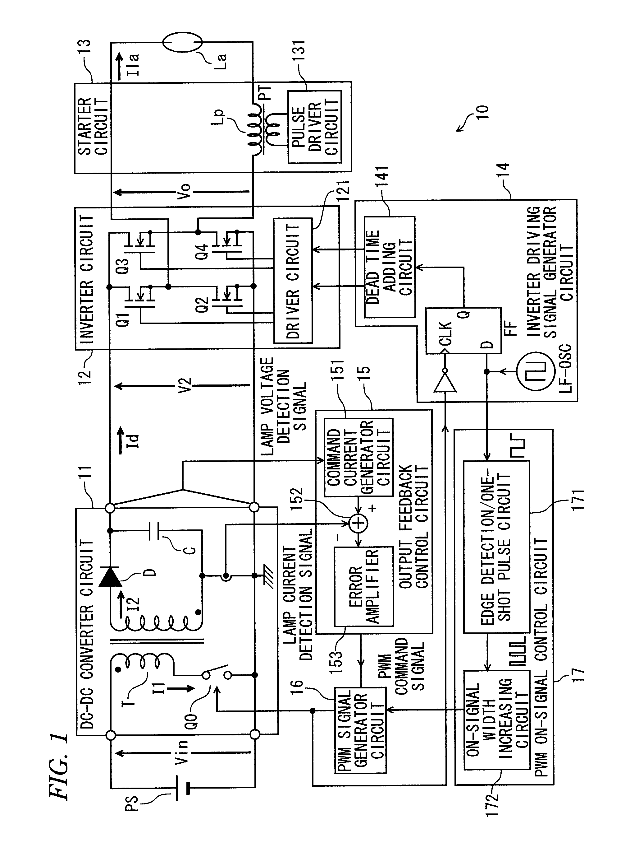
[0043]FIG. 1 is a schematic diagram of a discharge lamp ballast according to Embodiment 1 of the present invention.
[0044]In FIG. 1, a discharge lamp ballast 10 of the present embodiment includes a DC-DC converter circuit 11, an inverter circuit 12, a starter circuit 13, an inverter driving signal generator circuit 14, an output feedback control circuit 15, a PWM signal generator circuit 16, and a PWM ON-signal control circuit 17.
[0045]The DC-DC converter circuit 11 is of the fly-back converter system, and includes a series circuit which includes a primary winding of a transformer T and a switching element Q0 and which is connected between both terminals of a DC power supply PS. In the DC-DC converter circuit 11, the switching element Q0 is turned ON / OFF in response to a PWM signal from the PWM signal generator circuit 16, so that an induced voltage in the secondary winding of the transformer T is rectified and smoothed by a diode D and a smoothing capacitor C, whereby a DC power hav...
embodiment 2
[0075]FIG. 3 is a schematic diagram of a discharge lamp ballast according to Embodiment 2 of the present invention. In this case, the same reference symbols are appended to the constituent elements having the same functions as those in FIG. 1, and their explanation will be simplified or omitted herein.
[0076]In FIG. 3, a discharge lamp ballast 20 according to Embodiment 2 of the present invention includes a DC-DC converter circuit 21, an inverter circuit 22, the starter circuit 13, an inverter drive signal generator circuit 24, the output feedback control circuit 15, the PWM signal generator circuit 16, and the PWM ON-signal control circuit 17.
[0077]In the DC-DC converter circuit 21, the diode D is connected in an opposite direction as compared with the DC-DC converter circuit 11 of the discharge lamp ballast 10 of Embodiment 1 shown in FIG. 1, and accordingly the output voltage V2 is set at a negative potential with respect to the GND level.
[0078]The inverter circuit 22 includes the...
embodiment 3
[0096]FIG. 6 is a schematic diagram of a lighting unit according to Embodiment 3 of the present invention, and FIG. 7 is an external perspective view of a vehicle equipped with the lighting unit according to Embodiment 3 of the present invention.
[0097]In FIG. 6, a lighting unit 100 is configured such that the discharge lamp La fitted to a socket 102, a reflector plate 103 configured to reflect a light of the discharge lamp La ahead, and a light shielding plate 104 configured to prevent the glare are housed inside a box-shaped casing 101 with the front surface opened. A light emitted from the discharge lamp La is irradiated to the outside via a translucent cover 105 fitted to an opening portion on the front surface of the casing 101.
[0098]Also, the discharge lamp ballast 10 or 20 according to Embodiment 1 or Embodiment 2 is housed in the case and is fitted to the lower outside of the casing 101, and is connected to the socket 102 via a cable 106. The DC power supply PS including the ...
PUM
 Abstract
Description
Claims
Application Information
 - R&D
- Intellectual Property
- Life Sciences
- Materials
- Tech Scout
- Unparalleled Data Quality
- Higher Quality Content
- 60% Fewer Hallucinations
Browse by: Latest US Patents, China's latest patents, Technical Efficacy Thesaurus, Application Domain, Technology Topic, Popular Technical Reports.
© 2025 PatSnap. All rights reserved.Legal|Privacy policy|Modern Slavery Act Transparency Statement|Sitemap|About US| Contact US: help@patsnap.com