Apparatus And Method For Rotating-Sensor-less Identification Of Magneto-Mechanical Parameters Of An AC Synchronous Motor

a technology of ac synchronous motor and ac synchronous motor, which is applied in the direction of motor/generator/converter stopper, electronic commutator, dynamo-electric converter control, etc., can solve the problem that the mechanical characteristic quantity cannot be determined in normal operation, and achieve the effect of reducing the effect of inductive behavior, saving hardware costs, and optimizing the efficiency of motor control

Active Publication Date: 2012-02-16
BAUMULLER NURNBERG GMBH
View PDF14 Cites 9 Cited by
  • Summary
  • Abstract
  • Description
  • Claims
  • Application Information

AI Technical Summary

Benefits of technology

[0043]According to an advantageous further development the ratio of constant voltage U1d to test signal voltage U1q can be selected in such an optimal manner for achieving maximal amplitudes of the deflection movement at a height such that magnetomechanical characteristic quantities of an adjustable spring-mass system can be determined with a pre-determinable accuracy. During the supplying of the test signal into the d rotor coordinate direction no torque is produced in the machine, so that the rotor remains at first torque-free in its position. The constant voltage U1d is to be selected in a magnitude here such that the rotor can return “elastically” into its position of rest during the supplying of the test signal in q direction. A constant voltage that is too low would lead to an undesired rotation of the rotor opposite the stator, so that no purposeful d / q current supply could be carried out. A constant voltage that is too high compared to the test signal voltage U1q would lead to a stopping of the stator, so that no mechanical movement and therefore no self-induction would occur. Consequently, in both instances no mechanical characteristic quantities could be determined. Therefore, it is important that the amplitudes of the constant voltage and of the test signal are in an appropriate relationship. If the constant voltage in the d axis would be clearly too large, the effect would be like a mechanically stopped machine. The method described here is based on the fact that the machine can move out of the flux axis and independently return into it. To this end it can advantageously be conceivable to vary the ratio of constant voltage U1d to the test signal voltage U1q and / or to vary the height of the constant voltage U1d and to perform parameter identifications with changed voltage values, whereby the resulting parameters can be determined as average or weighted parameters from the results of the individual parameter identifications. Thus, errors can be reduced in the determination, so that a more precise result can be achieved.
[0055]According to an advantageous further development the apparatus can furthermore comprise a monitoring and optimization unit that is set up to determine, optimize and / or monitor control parameters of an inverter control apparatus on the basis of the identified magnetomechanical characteristic quantities. The monitoring and optimization unit receives the Identified characteristic quantities of the parameter identification unit and can optimize control parameters of the motor control device on the basis of the determined magnetomechanical characteristic quantities, in particular as regards a dynamic regulator behavior and / or filter properties in order to reduce the effects of the inductive behavior of the asynchronous motor on the mains. Furthermore, an efficient operation of the motor control can be optimized and motor changes monitored and / or an error signal can be emitted in the case of a motor failure or erroneous behavior.

Problems solved by technology

However, modern electrical drives regulated without a shaft encoder can not fall back on sensor data, so that mechanical characteristic quantities can not be determined in normal operation.

Method used


Image

  • Apparatus And Method For Rotating-Sensor-less Identification Of Magneto-Mechanical Parameters Of An AC Synchronous Motor
  • Apparatus And Method For Rotating-Sensor-less Identification Of Magneto-Mechanical Parameters Of An AC Synchronous Motor
  • Apparatus And Method For Rotating-Sensor-less Identification Of Magneto-Mechanical Parameters Of An AC Synchronous Motor

Examples


Embodiment Construction

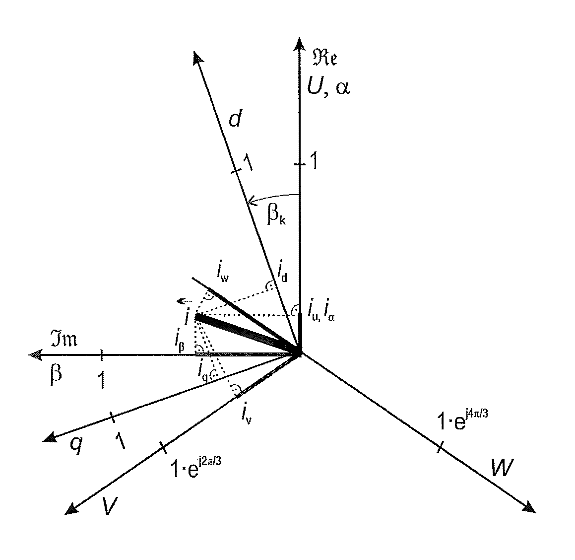
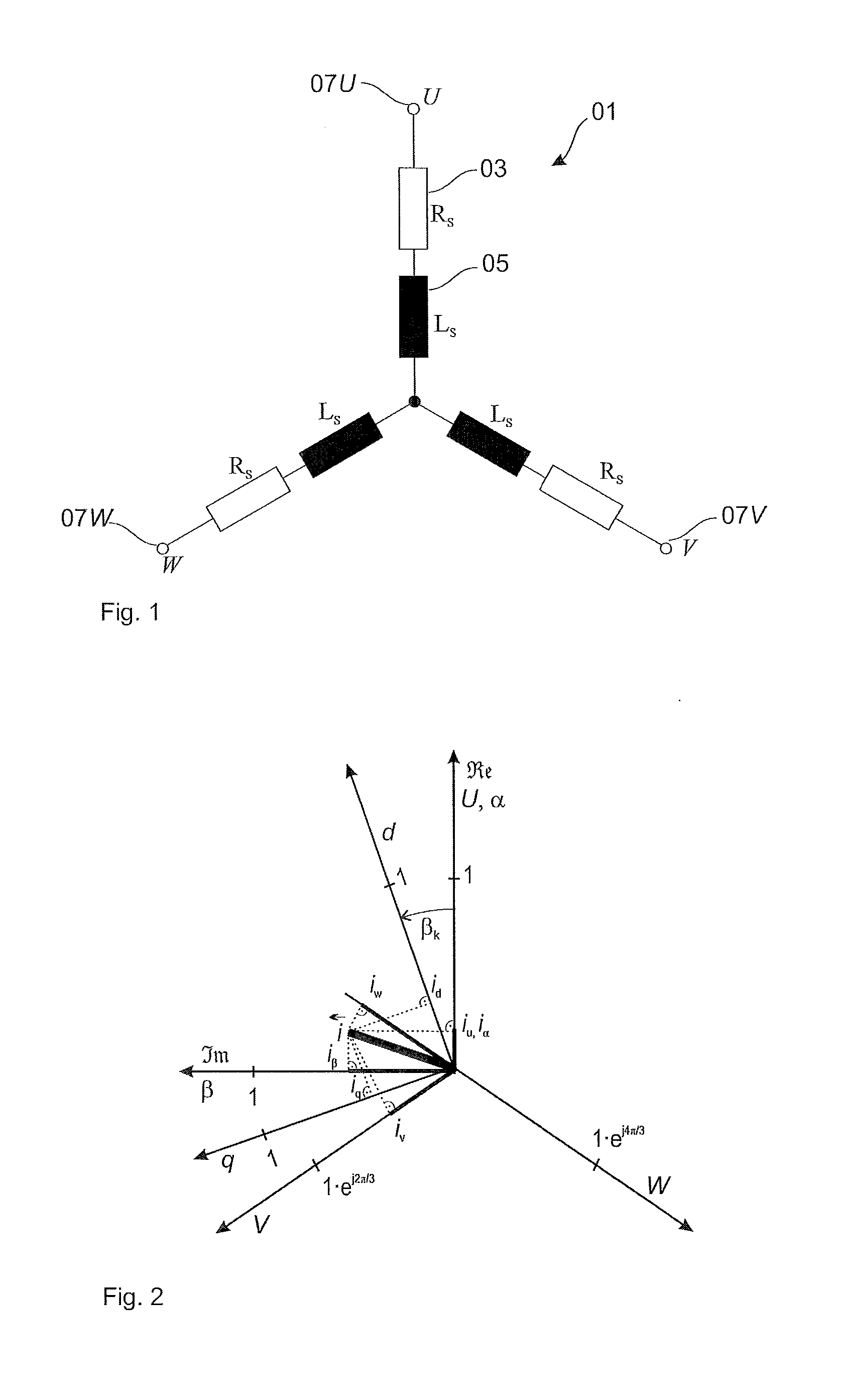
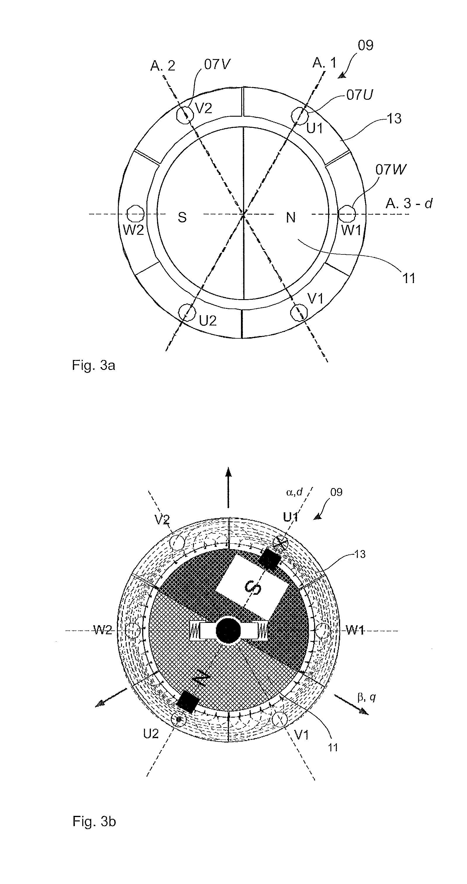
[0073]In the figures the same or similar components are designated with the same reference numbers. In order to explain the invention FIG. 1 shows an equivalent circuit of the stator coil 0103-phase motor. Each coil strand U, V and W comprises a coil resistor Rs 03 and a coil inductivity Ls 05. The three coil strands 07 are connected to each other at their first end and at their second end to the three phases U, V, W of the output of an inverter. The stator coil 01 integrates with the rotatably mounted rotor coil 11, that has a constant magnetizing in a d flux axial direction. The magnetic field of the rotor can be generated in a rotor winding by permanent magnets attached along the rotor circumference or by a direct current supplied via slip rings. The magnetic field of the rotor adheres to the rotating magnetic field of the stator and thus allows the rotor to rotate in the frequency of the magnetic field of the stator. The system of rotor coil 11 and stator coil 01 can be consider...


PUM


Abstract

A method for the identification without a shaft encoder of magnetomechanical characteristic quantities, in particular the mass moment of inertia J and the permanent magnetic flux ψPM between rotor and stator of a three-phase synchronous motor, comprising: —constant voltage supply U1d in the d flux axial direction; —test signal voltage supply U1q in the q transverse flux axial direction; —measuring signal current measuring I1q of the q transverse flux axial direction; —identification of magnetomechanical characteristic quantities of the synchronous motor on the basis of the test signal voltage U1q and of the measuring signal current I1q; whereby the rotor can execute deflection movements with pre-definable maximal amplitudes. Method use also for control of electrical drives. An identification apparatus for determination of magnetomechanical characteristic quantities (79) of a synchronous motor (09) that also relates to a motor control device, whereby the identified characteristic quantities can be used for the determination, optimization and monitoring of a motor control.

Description

[0001]The present invention starts from a method, a device, an apparatus and the use of a method for an identification of magnetomechanical characteristic quantities, in particular the mass moment of inertia J of the rotor and permanent magnetic flux ψPM between rotor and stator of a three-phase synchronous motor. Magnetomechanical characteristic quantities make possible the characterization of a three-phase motor relative to the magnetic interaction between stator and rotor and make possible mechanical dynamic behaviors, so that both the magnetic as well as the mechanical and rotational behaviors of the motor can be characterized during operation.STATE OF THE ART[0002]Various methods are known from the state of the art for determining the magnetic and the mechanical behavior of a three-phase motor. As a rule sensor data from position transmitters, angle of rotation transmitters or engine speed sensors are evaluated for the determination of the mechanical behavior, and the mass mome...

Claims


Application Information

Patent Timeline
Patent Type & Authority Applications(United States)
IPC IPC(8): H02P6/08
CPCG01R31/34H02P23/14H02P2207/05H02P21/16
Inventor VILLWOCK, SEBASTIANZATOCIL, HEIKO
Owner BAUMULLER NURNBERG GMBH
Why Eureka
Try Eureka