Liquid leakage propagation restraining structure for electricity storage device and bus bar module

a technology of electricity storage device and restraining structure, which is applied in the direction of secondary cell servicing/maintenance, cell components, instruments, etc., can solve the problems of insufficient countermeasure against leakage of electrolytic solution, inability to carry out complete sealing, and difficulty in sealing against liquid leakag

Inactive Publication Date: 2012-02-16
TOYOTA JIDOSHA KK +1
View PDF2 Cites 19 Cited by
  • Summary
  • Abstract
  • Description
  • Claims
  • Application Information

AI Technical Summary

Benefits of technology

[0031]According to the first aspect, since the voltage detection terminal is connected to an adjacent one of the electrodes of the electricity storage device so that the crimp contact surface of the voltage detection terminal to which an electric cable is crimped faces in the direction opposite the direction to the electrode, it is possible to restrain the electrolytic solution that leaks at the electrode from entering the core wire of the electric cable via the electric cable.
[0032]According to the second aspect; since the voltage detection terminal is electrically connected to the electrode that is on the positive electrode side of the electricity storage device, it is possible to make it less likely that leakage of the electrolytic solution from the negative electrode side propagates to the voltage detection terminal by the negative electrode creep phenomenon in batteries that use an alkaline electrolytic solution, such as nickel metal hydride storage batteries (Ni-MH batteries), nickel cadmium storage batteries (Ni—Cd batteries), etc.
[0033]According to the third aspect, since the sump portion (gap) is provided in the wiring space in which the electric cable and / or the crimp contact portion of the voltage detection terminal in the bus bar module is disposed, a clearance is given between the wall of the wiring space and the crimp contact portion and / or the electric cable, so that the electrolytic solution that leaks is less likely to propagate to the voltage detection terminal. Besides, the sump portion serves as a sealing material fill-in space into which the sealing material is to be charged or placed. Therefore, it is possible to take a countermeasure against leakage of the electrolytic solution at the use of a sealing material.
[0034]According to the fourth aspect, since the crimp contact portion of the voltage detection terminal (to which the electric cable is crimped) is sealed, entrance of the electrolytic solution into the interior of the core wire of the electric cable (the voltage detection line) can be restrained even in the case where the electrolytic solution has reached the crimp contact portion. Incidentally, while the crimp contact portion can be sealed by soldering, this is not restrictive. For example, adhesive and other sealing materials can be used. Due to this, it becomes less likely that the electrolytic solution that leaks propagates to other electric component parts.

Problems solved by technology

This sometimes results in a malfunction or the like due to the exposure of an electric cable or a voltage detection terminal of a bus bar module to the electrolytic solution, for example, a problem in the functions of the battery due to leakage of the electrolytic solution (liquid leakage) propagating to another electric component part via the electric cable, or due to leakage of the electrolytic solution moving at the core wire of the electric cable.
Furthermore, as for batteries, the countermeasure against leakage of the electrolytic solution is not sufficient.
Therefore, the structure undesirably allows the leaking electrolytic solution to easily enter the core wire of the electric cable.
However, it is known that the alkaline electric solution exhibits a creep phenomenon in which the electrolytic solution creeps on a metal surface, and therefore makes complete sealing very difficult.
Thus, the sealing against the liquid leakage cannot be carried out.

Method used


Image

  • Liquid leakage propagation restraining structure for electricity storage device and bus bar module
  • Liquid leakage propagation restraining structure for electricity storage device and bus bar module
  • Liquid leakage propagation restraining structure for electricity storage device and bus bar module

Examples


first embodiment

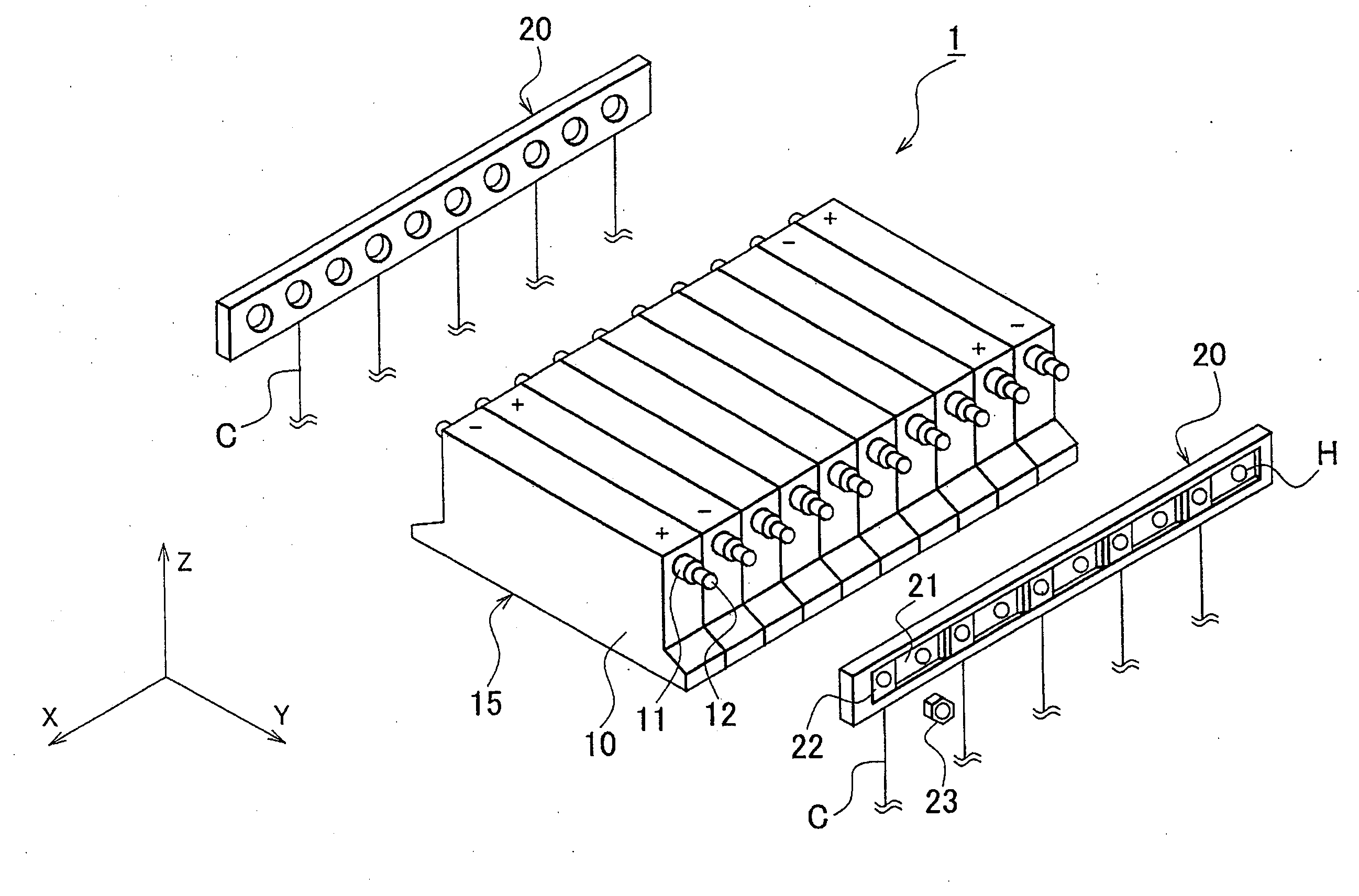
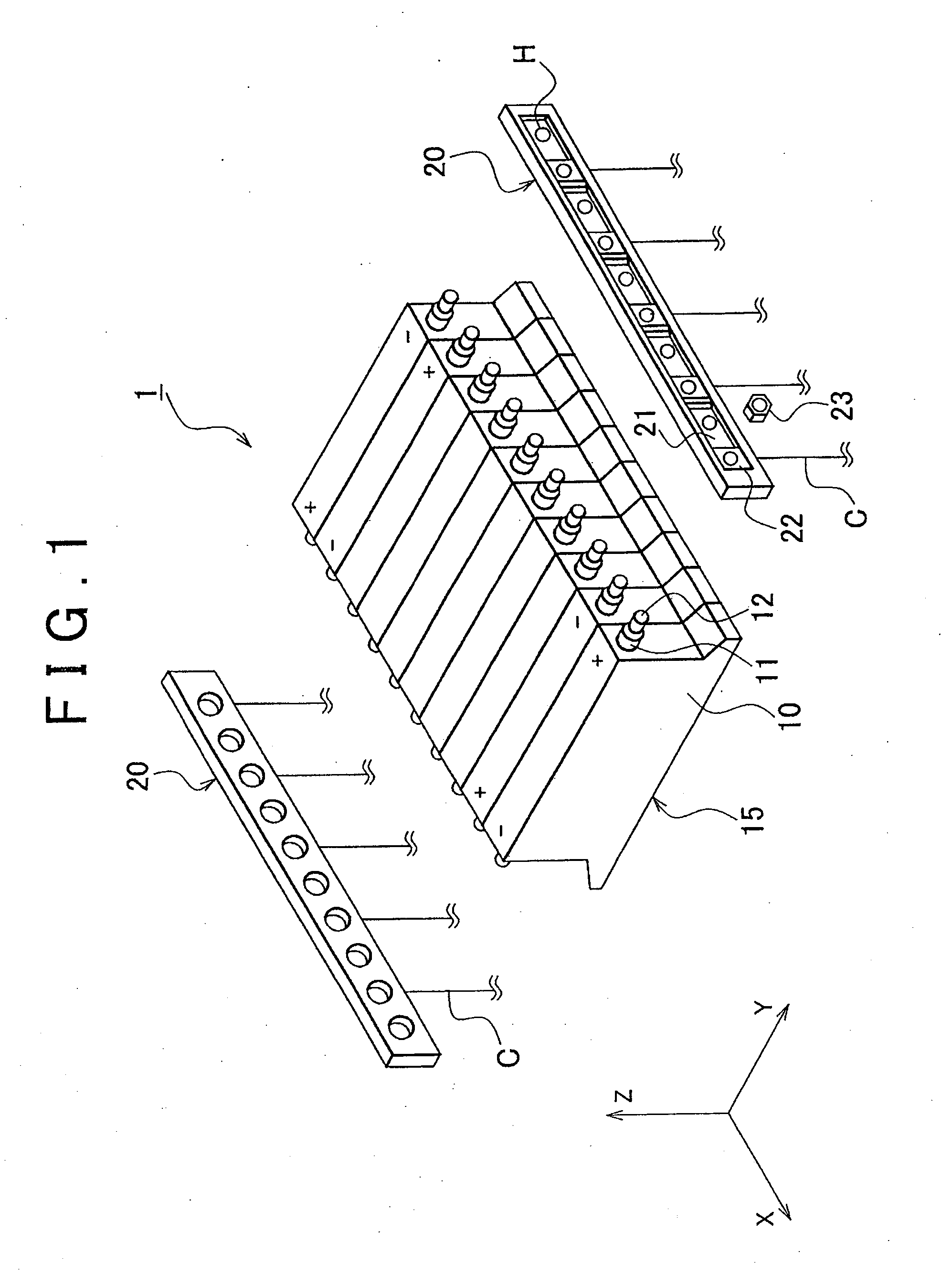
[0047]FIG. 1 is an exploded perspective view of an electricity storage device 1 to which the liquid leakage propagation restraining structure and the bus bar module of the invention are applied. The electricity storage device 1 includes a battery assembly (electricity storage assembly) 15 constructed of a plurality of electric cells 10, and bus bar modules 20 that electrically connect positive electrodes P (+) and negative electrodes N (−) of the electric cells 10 and that connects the electric cells of the entire battery assembly 15 in series.

[0048]The electricity storage device 1 is used as an electric power supply device mounted in a hybrid vehicle or an electric motor vehicle, such as a secondary battery that uses an alkaline electrolytic solution, including a nickel metal hydride storage battery (Ni-MH battery), a nickel cadmium storage battery (Ni—Cd battery), etc., a lithium ion secondary battery, an electric double layer capacitor, etc. Each electric cell 10 contains therein...

second embodiment

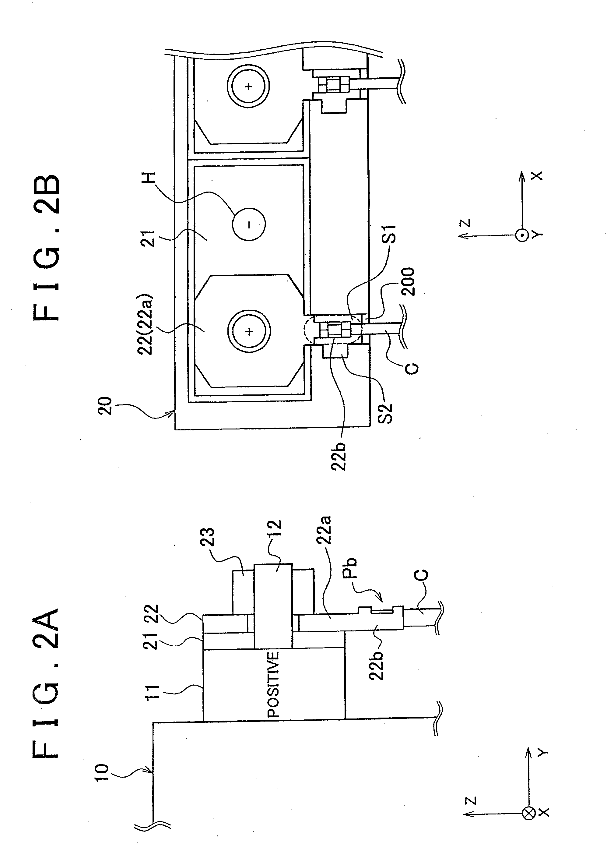
[0063]FIGS. 3A to 3C are diagrams illustrating the voltage detection terminal 22 in a second embodiment. FIG. 3A is a diagram illustrating the soldering connection of the voltage detection terminal 22. FIG. 3B is a perspective view of the voltage detection terminal 22. FIG. 3C is a cross-sectional view of an electric cable.

[0064]In the voltage detection terminal 22 in this embodiment, a crimp contact leg portion 221b (front leg) and another crimp contact leg portion 222b (rear leg) are entirely covered and sealed with solder (indicated by hatching in FIG. 3A), so that leakage of the electrolytic solution will not enter the core wire of the electric cable C. That is, generally in the related art, the electric cable C is connected by crimping to the crimp contact portion 22b via the crimp contact leg portions 221b and 222b, and the crimp contact leg portion 221b that is near the electric contact portion22a is soldered (i.e., only a portion to which exposed core wire C1 is electrically...


PUM

PropertyMeasurementUnit
voltageaaaaaaaaaa
lengthaaaaaaaaaa
diameteraaaaaaaaaa

Abstract

In a liquid leakage propagation restraining structure, a voltage detection terminal that detects the voltage of an electricity storage device is connected to an electrode of the electricity storage device so that a crimp contact surface side of the voltage detection terminal to which an electric cable is crimped faces in the direction opposite the direction to the electrode. Therefore, the structure restrains the electrolytic solution that has leaked out and propagated to the electric cable from entering the interior of the core wire of the electric cable.

Description

BACKGROUND OF THE INVENTION[0001]1. Field of the Invention[0002]The invention relates to a liquid leakage propagation restraining structure for an electrolytic solution of an electricity storage device, such as a secondary battery or the like, and also relates to a bus bar module.[0003]2. Description of the Related Art[0004]As described in Japanese Patent Application Publication No. 2000-333343 (JP-A-2000-333343) (FIG. 7, FIG. 8, FIG. 14, etc.), in a battery, such as a secondary battery or the like, which is mounted in a hybrid motor vehicle or an electric motor vehicle, bus bar modules (battery connection modules) are attached to both sides of a battery assembly so as to connect in series a plurality of electric cells that constitute the battery assembly. The bus bar modules are formed from a synthetic resin or the like. Each bus bar module is provided with bus bars each of which electrically connects an electrode of an electric cell and an electrode of another electric cell, and w...

Claims


Application Information

Patent Timeline
Patent Type & Authority Applications(United States)
IPC IPC(8): G01N27/416H01M50/507H01M50/51H01M50/522H01M50/524H01M50/569H01M50/571
CPCH01M2/206H01M2/32H01M10/4228H01M10/482H01R4/023H01R4/187H01R4/20Y02E60/10H01M50/571H01M50/522H01M50/507H01M50/51H01M50/569H01M50/524
Inventor NAGATA, SHUICHITSUSHIMA, MANABUWATANABE, SHIGENORISHOJI, TAKAOYAMAZAKI, HIKOHITOIKEDA, TOMOHIRO
Owner TOYOTA JIDOSHA KK
Why Eureka
Try Eureka