Temperature sensor unit and a method for making the same

a temperature sensor and temperature technology, applied in the field of temperature sensor units, can solve the problems of temperature sensor breaking down, prone to breakage of the terminals of the temperature sensor to electrical conductors, etc., and achieve the effects of reducing the risk of damage to the temperature sensor, less viscosity, and better fi

Active Publication Date: 2012-02-16
DANFOSS AS
View PDF10 Cites 16 Cited by
  • Summary
  • Abstract
  • Description
  • Claims
  • Application Information

AI Technical Summary

Benefits of technology

[0023]One further advantage of the present invention is that the less viscous the insulator is at in its liquid state, the better the fit between the sheath, the insulator and the temperature sensor may be as any air pockets may escape more easily. It will be appreciated that this reduces the risk of damage of the temperature sensor even further due to the improved fit.
[0024]The step of positioning the sensors may precede the step of providing the second insulating material such that the second insulating material is poured into the sheath when the sensors are already provided in the previously mentioned space.
[0025]Alternatively, the step of providing the second insulating material may precede the step of positioning the sensors. In one embodiment, the step of positioning the sensors comprises the step of positioning the sensors in the second insulating material while the second insulating material is in liquid form.
[0026]In one embodiment, the step of providing the conductors comprises the step of: providing a sheath in which the set of conductors are already retained relative to the sheath by means of ...

Problems solved by technology

In such an environment, the solderings/weldings of the terminals of the temperature sensor to electrical ...

Method used


Image

  • Temperature sensor unit and a method for making the same
  • Temperature sensor unit and a method for making the same
  • Temperature sensor unit and a method for making the same

Examples


Embodiment Construction

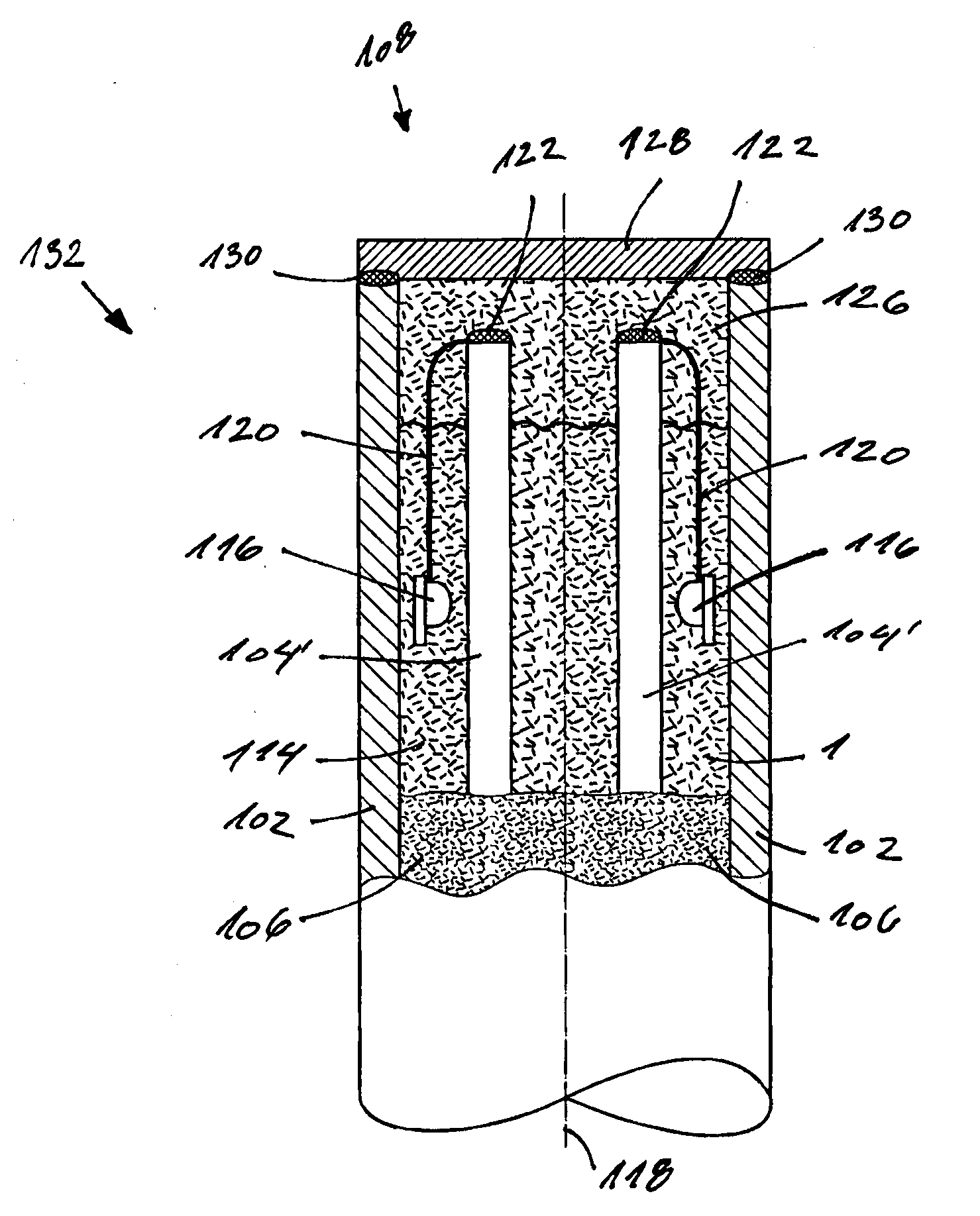
[0065]The below description of the figures illustrates an embodiment of the manufacturing process according to the first aspect of the invention. An embodiment of the product according to the second aspect is disclosed in FIG. 8.

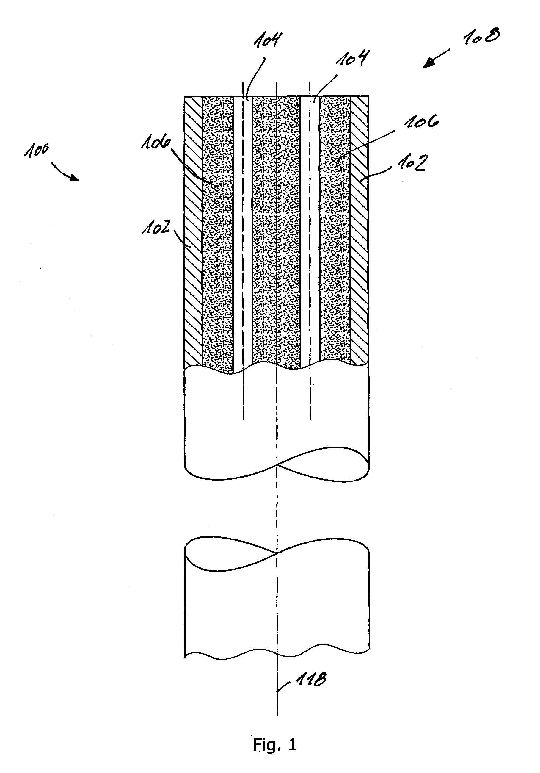
[0066]FIG. 1 discloses a prefabricated tube 100 comprising a sheath 102 in which the conductors 104 are retained by means of a first insulating material 106, e.g. hard pressed sand. Initially, only a distal end 108 of the prefabricated tube 100 is cut. Then the prefabricated tube 100 is cut into a piece of a desired length. This piece forms the distal end 108 and a proximal end (not disclosed). In the embodiment of FIGS. 1-8, four conductors 104 are provided, but due to the viewing angle only two of the conductors are visible in FIG. 1.

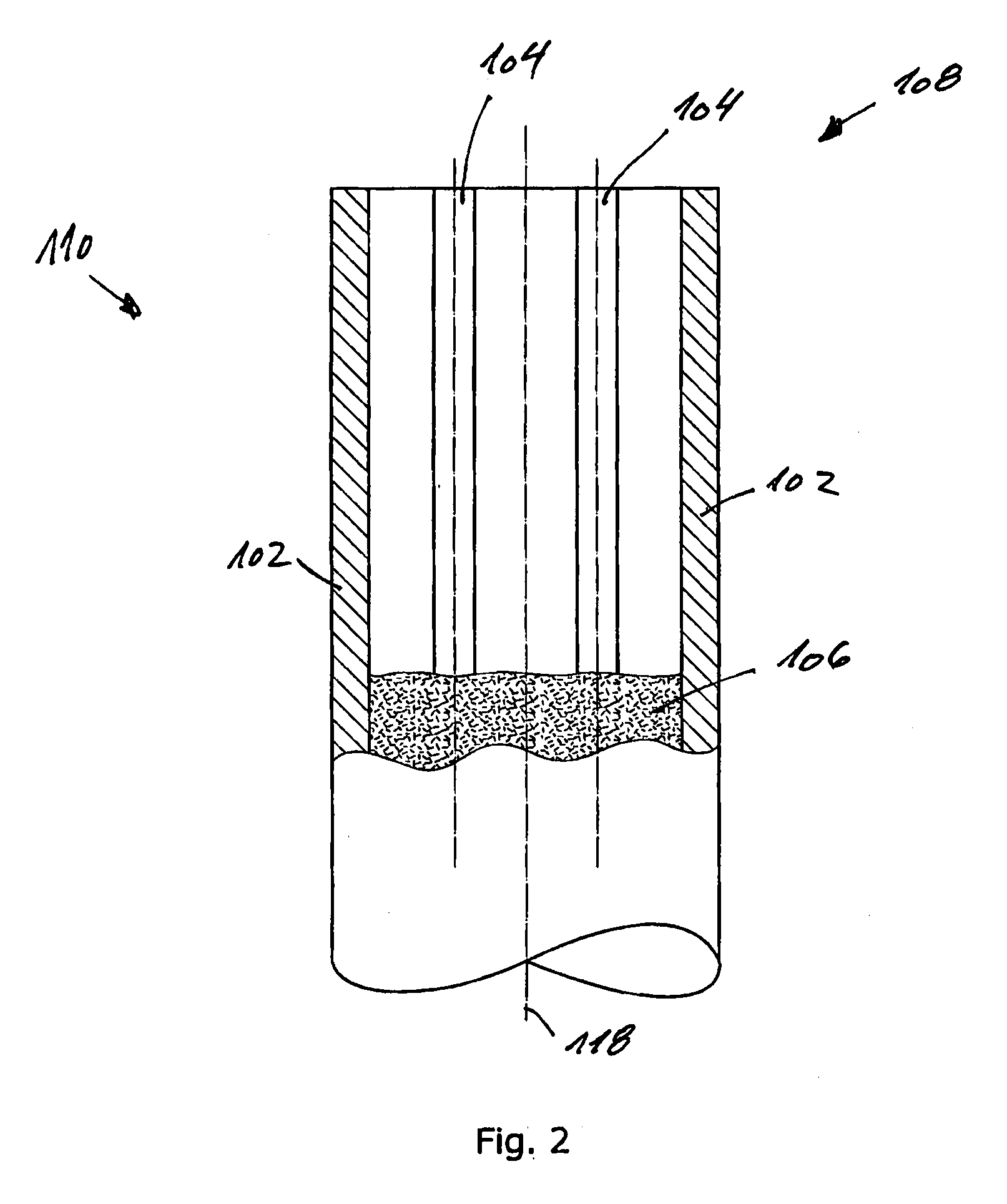
[0067]FIG. 2 discloses the tube piece 110 resulting from cutting the prefabricated tube 100 of FIG. 1. In FIG. 2, a part of the first insulating material 106 has been removed from the distal end 108 of the tube piece 110 where...


PUM

PropertyMeasurementUnit
Transmittivityaaaaaaaaaa
Lengthaaaaaaaaaa
Widthaaaaaaaaaa

Abstract

A method of manufacturing a temperature sensor unit comprising the steps of: providing the conductors in the sheath such that in a first zone a space is defined between the sheath and the conductors; providing the second insulating material in liquid form in the space; positioning the sensors in the space such that the conductors are provided closer to the centre of the sheath than the sensors; and soldering and/or welding the set of conductors to the set of terminals. A temperature sensor in which sets of conductors and one or more temperature sensors are arranged inside a sheath and with respect to each other such that the conductors are provided closer to the centre of the sheath than the temperature sensors.

Description

CROSS REFERENCE TO RELATED APPLICATIONS[0001]This application is entitled to the benefit of and incorporates by reference essential subject matter disclosed in International Patent Application No. PCT / DK2010 / 000029 filed on Mar. 11, 2010 and Danish Patent Application No. PA 200900356 filed Mar. 13, 2009.FIELD OF THE INVENTION[0002]The present invention relates to a temperature sensor unit with a temperature sensor provided in a sheath and an insulating material provided in the space between the sheath and the temperature sensor. Moreover the present invention relates to a method of manufacturing the temperature sensor unit.BACKGROUND OF THE INVENTION[0003]Temperature sensors are known to be used to monitor operation of apparatuses with a high temperature environment. As an example, this could e.g. be an engine of an automobile in which it is desirable that the engine does not overheat.[0004]One example of such a high temperature sensor is known form U.S. Pat. No. 4,087,775 which dis...

Claims


Application Information

Patent Timeline
IPC IPC(8): G01K1/08B23K26/20H01R43/02
CPCY10T29/49179G01K1/08G01K7/18
Inventor PEDERSEN, SVEND PEDERDYHR, JAN
Owner DANFOSS AS
Why Eureka
Try Eureka