Implantable Devices and Methods for Measuring Intraocular, Subconjunctival or Subdermal Pressure and/or Analyte Concentration

a technology of subconjunctival or subdermal pressure and analyte concentration, which is applied in the field of measuring intraocular pressure, can solve problems such as the change in the wavelength of light reflected by the reflective member, and achieve the effect of facilitating drainage of aqueous humor

Inactive Publication Date: 2012-02-16
BCC ENTERPRISE
View PDF16 Cites 74 Cited by
  • Summary
  • Abstract
  • Description
  • Claims
  • Application Information

AI Technical Summary

Problems solved by technology

This results in changes in the wavelength of the light reflected by the reflective member.

Method used


Image

  • Implantable Devices and Methods for Measuring Intraocular, Subconjunctival or Subdermal Pressure and/or Analyte Concentration
  • Implantable Devices and Methods for Measuring Intraocular, Subconjunctival or Subdermal Pressure and/or Analyte Concentration
  • Implantable Devices and Methods for Measuring Intraocular, Subconjunctival or Subdermal Pressure and/or Analyte Concentration

Examples


example 1

Intraocular Pressure Sensing System

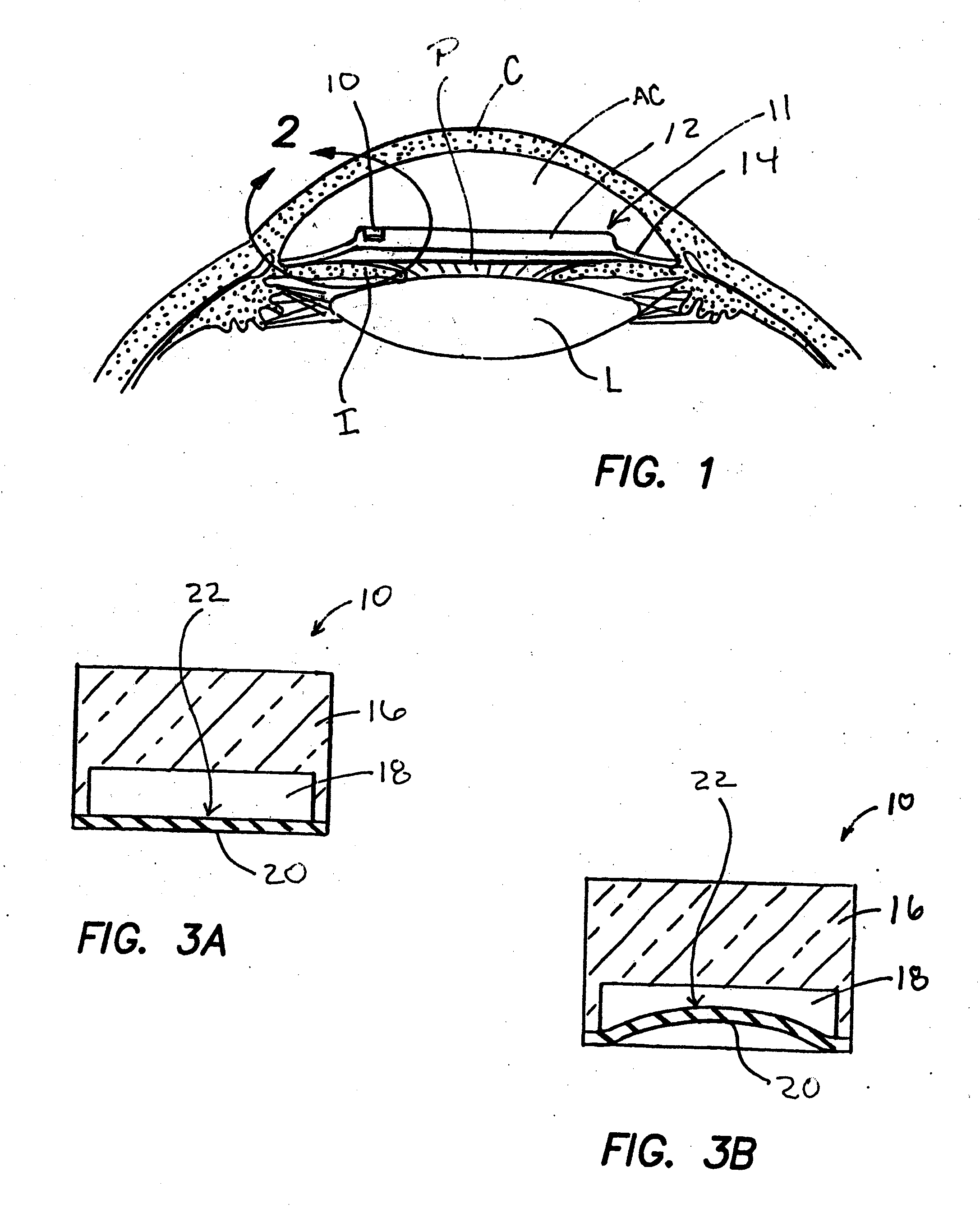
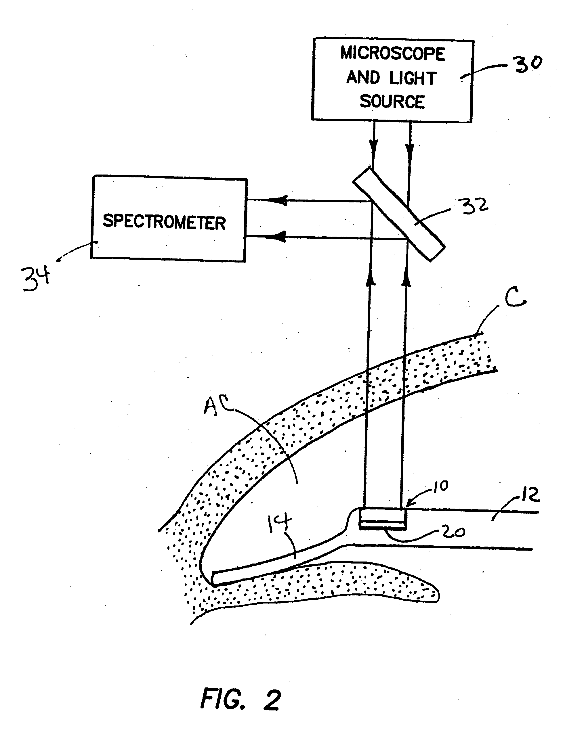
[0031]An intraocular pressure sensing system of the present invention is shown in FIGS. 1-3b. As may be seen in FIG. 1, an optical pressure sensor 10 is mounted on a support 11. This support 11 comprises a haptic 14 and an optic 12, in the nature of a typical phakic intraocular lens adapted for implantation within the anterior chamber AC of the eye. In the embodiment shown, the optical pressure sensor 10 is attached to one edge of the optic 12, but it is to be appreciated that the optical pressure sensor could also be attached to the optic 12 and / or haptic 14 at other locations or in other ways. The optic may or may not provide some refractive vision correction in addition to performing the function of a support 11 for the optical pressure sensor 10. On example of a 2-piece phakic intraocular lens that may be used to form the support 11 is the Kelman Duet Implant manufactured by TEKIA, Inc., Irvine, Calif.

[0032]The support11 holds the optical press...

example 2

Intraocular Analyte Determining System

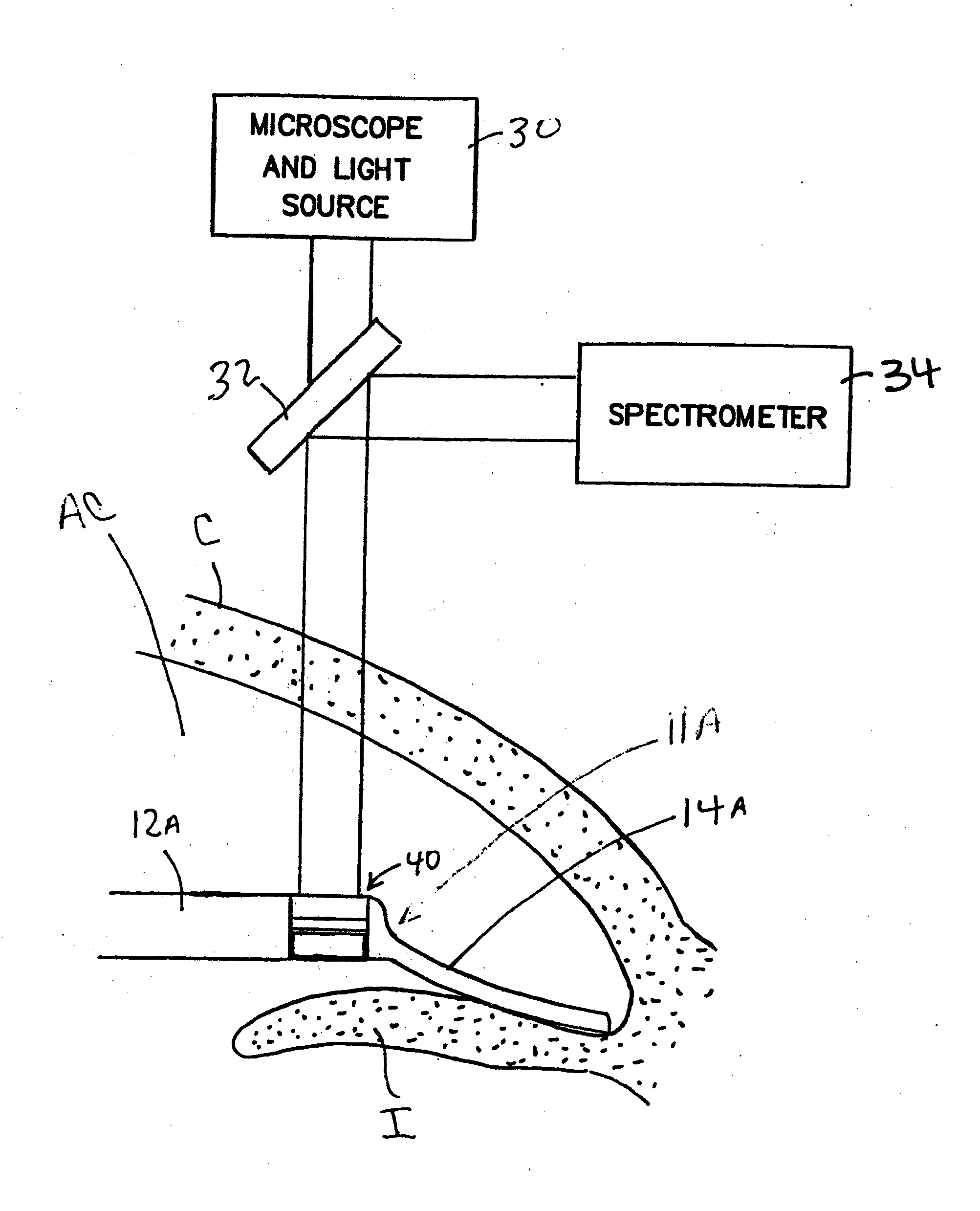
[0039]FIGS. 8, 9A and 9B show a system for quantitative or qualitative determination of an analyte within the eye of a human or veterinary patient. This system comprises an optical analyte sensor 40 that is implanted within the eye. This optical analyte sensor 40 may be configured for implantation as a stand alone device or may be attached to a support 11A. In the particular embodiment shown, the support 11A comprises an intraocular lens system that comprises an optic 12a and a haptic 14a, of the same type as described hereabove in reference to FIG. 2.

[0040]The optical analyte sensor 40 is shown in detail in FIGS. 9A and 9B. As shown, the optical analyte sensor 40 comprises a translucent body 46 (or an opaque body having a translucent window) having a hollow cavity 48 formed at one end thereof. One or more walls of the cavity 48, or at least a portion of one wall of the cavity 48, is / are formed of a semipermeable membrane 50 through which a part...

example 3

Combined System for Measuring Intraocular Pressure and Analyte Concentration

[0043]FIG. 10 shows another embodiment of the present invention wherein both the optical pressure sensor 10 and optical analyte sensor 40 are attached to a common support 11B that comprises an intraocular lens assembly implanted in the anterior chamber Ac of a patient's eye. The support includes an optic 12b and haptic 14c which may be the same as those described above with respect to FIG. 2.

[0044]In this embodiment wherein the optical pressure sensor 10 and the optical analyte sensor 40 are used in combination, a single light source 30 or separate light sources 30, may be used to cast light on the reflective surfaces 22 and 44 of the optical pressure sensor diaphragm 20 and the optical analyte sensor diaphragm 40, respectively. In embodiments where a single light source is used, such single light source may be adjustable to vary the direction, wavelength and / or other characteristics of the of the light beam...


PUM


Abstract

Methods, apparatus and systems for measuring pressure and / or for quantitative or qualitative measurement of analytes within the eye or elsewhere in the body. Optical pressure sensors and / or optical analyte sensors are implanted in the body and light is cast from an extracorporeal light source, though the cornea, conjunctiva or dermis, and onto a reflective element located within each pressure sensor or analyte sensor. The position or configuration of each sensor's reflective element varies with pressure or analyte concentration. Thus, the reflectance spectra of light reflected by the sensors' reflective elements will vary with changes in pressure or changes in analyte concentration. A spectrometer or other suitable instrument is used to process and analyze the reflectance spectra of the reflected light, thereby obtaining an indication of pressure or analyte concentration adjacent to the sensor(s). The wavelength of the interrogating beam of light may vary to control out potential interference or inaccuracies in the system.

Description

RELATED APPLICATIONS[0001]This application is a division of copending U.S. patent application Ser. No. 10 / 754,479 filed Jan. 9, 2004, which claims the benefit of U.S. Provisional Application Ser. No. 60 / 439,307 filed Jan. 9, 2003 and 60 / 439,308 filed Jan. 9, 2003, the entire disclosure of each such prior application being expressly incorporated herein by reference.BACKGROUND OF THE INVENTIONMeasurement of Intraocular Pressure[0002]The term “glaucoma” encompasses a group of diseases, which cause progressive damage to the optic nerve and resultant optical field defects, vision loss and, in some cases, blindness. Typically, glaucoma is frequently, but not always, accompanied by abnormally high intraocular pressure.[0003]There are three basic types of glaucoma—primary, secondary and congenital. The most common type of glaucoma is primary glaucoma. Cases of primary glaucoma can be classified as either open angle or closed angle.[0004]Secondary glaucoma occurs as a complication of a varie...

Claims


Application Information

Patent Timeline
Patent Type & Authority Applications(United States)
IPC IPC(8): A61B3/16A61F9/00A61B5/00A61F2/16A61BA61B1/00
CPCA61B3/16A61B5/0084A61B5/686A61B5/6867A61F2/14A61F2/16A61F2002/1681
Inventor CHUCK, ROY S.BAERVELDT, GEORGECHOU, JIM-SON
Owner BCC ENTERPRISE
Why Eureka
Try Eureka