Low rate, direct conversion fsk radio-frequency signal receiver

a radio frequency signal and receiver technology, applied in the field of low rate and direct conversion radio frequency signal receivers, can solve the problems of high frequency, high electric power consumption of the receiver, and the need for a low-pass filter with a very broad bandwidth, and achieve low power consumption, high sensitivity, and low rate mode

Active Publication Date: 2012-02-23
THE SWATCH GRP RES & DEVELONMENT LTD
View PDF2 Cites 11 Cited by
  • Summary
  • Abstract
  • Description
  • Claims
  • Application Information

AI Technical Summary

Benefits of technology

[0010]It is thus an object of the invention to provide a direct conversion radio frequency signal receiver for FSK modulation, which has a high level of sensitivity in a low rate mode and low power consumption, to overcome the aforementioned drawbacks of the state of the art.

Problems solved by technology

Since high frequency direct conversion is carried out in the two mixers 4 and 5, followed by filtering in the two low-pass filters and amplitude limiting in two limiters, the receiver consumes a high level of electric power, which is a drawback.
This leads to high frequencies.
In these conditions, because very rapid switching is required, a low-pass filter with a very broad bandwidth is needed after the single mixer, which is a drawback.
This also means that the FSK signal receiver has low practical sensitivity and poor reception channel efficiency, but high electric power consumption.
This receiver can only be used for controlling equipment in a precise place, but not in a communication universe with several transmission and reception channels.
These spurious frequencies may even be higher than the frequency of the incoming radio frequency signals, which leads to high power consumption in the receiver input stage.
This is a drawback, since second low-pass filters with a narrow bandwidth must also be provided before the data demodulation phase to remove all of the spurious frequencies, which have not been filtered out by the first low-pass filter.
High power consumption in the input stage, notably the phase control circuit, is thus observed, and additional components are provided between the frequency conversion and data demodulation, which is another drawback.

Method used


Image

  • Low rate, direct conversion fsk radio-frequency signal receiver
  • Low rate, direct conversion fsk radio-frequency signal receiver
  • Low rate, direct conversion fsk radio-frequency signal receiver

Examples


first embodiment

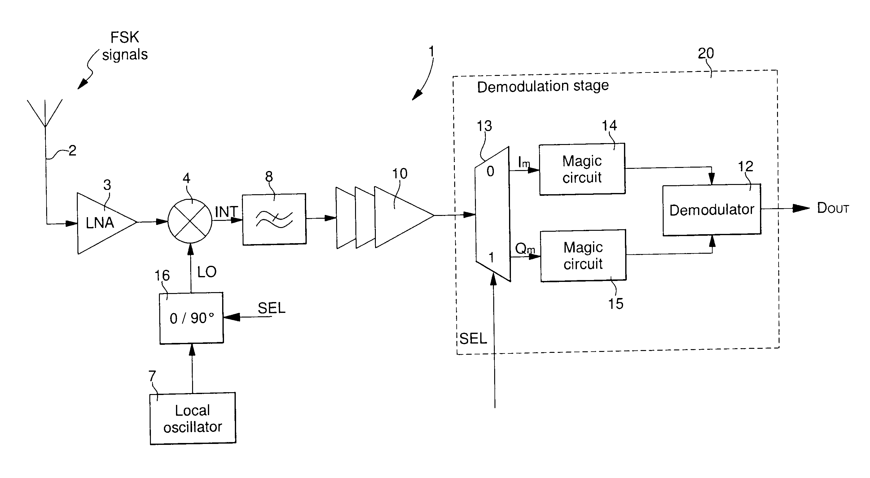
[0034]the FSK radio frequency signal receiver 1 is shown in FIG. 2a. The receiver of FIG. 2a includes first of all, an FSK radio frequency signal receiver antenna 2 and an LNA 3 for conventional amplification and filtering of the FSK signals. The receiver also includes a local oscillator 7 for providing oscillating signals LO to a phase shift circuit 16. The oscillating signals LO are generated with an equivalent frequency to the carrier frequency f0 of the incoming FSK signals. Phase shift circuit 16 is controlled by a phase selection signal SEL so as to phase shift from 0° to 90° or vice versa the oscillating signals LO supplied by local oscillator 7 in each semi-period of a switching cycle 1 / fs. This enables a single mixer 4 to be supplied alternately with in-phase oscillating signals and quadrature oscillating signals, which are phase shifted 90° relative to the in-phase oscillating signals.

[0035]The in-phase oscillating signals are, for example, supplied when the signal SEL is ...

second embodiment

[0054]FIG. 5 describes a second simplified embodiment of a local oscillator, which integrates the phase shift circuit for the FSK radio frequency signal receiver of FIG. 2a. This local oscillator is preferably a frequency synthesiser with two delay units 46 and 47 that can be switched by phase selection signal SEL. Since several components of the frequency synthesiser of this second embodiment are identical to those described with reference to FIG. 4a, for the sake of simplicity, the description thereof will not be repeated.

[0055]The difference between this second embodiment of the frequency synthesiser and the first embodiment described above with reference to FIG. 4a is thus that two switchable delay units 46 and 47 are used instead of the sigma-delta modulator. The oscillating signals LO generated by VCO 34 are divided in a standard divider-by-N or a multi-mode divider 45 as desired, before the divided signals are directed to the input of the first delay unit 46 and the second de...

third embodiment

[0057]FIG. 6 describes a third simplified embodiment of a local oscillator, which integrates the phase shift circuit for the FSK radio frequency signal receiver of FIG. 2a. This local oscillator is preferably a frequency synthesiser with two delay units 56 and 57 that can be switched by phase selection signal SEL. Since several components of the frequency synthesiser of this third embodiment are identical to those described with reference to FIGS. 4a and 5, for the sake of simplicity, the description thereof will not be repeated.

[0058]This third embodiment of the frequency synthesiser is very similar to the second embodiment shown in FIG. 5. In this third embodiment, the two delay units 56, 57 are arranged this time between the reference oscillator 30 and the phase and frequency detector 31. The oscillating signals LO generated by VCO 34 are only divided by the programmable or multi-mode divider 55. This programmable divider 55 supplies divided signals to the phase and frequency det...


PUM


Abstract

The receiver (1) picks up low rate FSK radio frequency signals. This receiver includes an antenna (2) for receiving FSK radio frequency signals, a low noise amplifier (3) connected to the antenna, a local oscillator (7) for supplying oscillating signals (LO), a phase shift circuit (16) for performing a 0° to 90° phase shift, and vice versa, in the oscillating signals (LO) or the incoming FSK radio frequency signals in each semi-period of a phase switching cycle (1/fs). The phase shift circuit alternately and successively generates in-phase and quadrature oscillating signals, or in-phase and quadrature incoming FSK radio frequency signals. The receiver includes a single mixer (4) for mixing the oscillating signals successively with the incoming FSK radio frequency signals, so as to generate alternately intermediate in-phase and quadrature baseband signals (INT) as a function of the phase shift circuit. The receiver further includes a low-pass filter (8) for filtering the intermediate in-phase and quadrature signals, and a demodulation stage (20) for demodulating the data (DOUT) from the filtered intermediate signals. The receiver is arranged such that the phase shift circuit (16) is switched by a phase selection signal (SEL) to a phase switching cycle frequency (fs) which is lower than the frequency deviation (Δf) of the modulated data in the FSK radio frequency signals and higher than the data rate frequency. Magic circuits (14, 15) in the demodulation stage reconstruct the intermediate signals during each switch operation for continuous demodulation in the demodulator (12).

Description

[0001]This application claims priority from European Patent Application No. 10173249.3 filed Aug. 8, 2010, the entire disclosure of which is incorporated herein by reference.FIELD OF THE INVENTION[0002]The invention concerns a low rate and direct conversion radio frequency signal receiver for FSK modulation.BACKGROUND OF THE INVENTION[0003]In a conventional radio frequency signal receiver for FSK modulation, as shown in FIG. 1a, direct frequency conversion can be carried out in two distinct quadrature branches to obtain baseband signals. Each branch includes a mixer 4, 5 for performing the frequency conversion with oscillating signals supplied by a local oscillator 7. In a first branch, a first high frequency mixer 4 mixes the FSK signals picked up by the antenna 2 and amplified by the low noise amplifier (“LNA”) 3 of the receiver, with in-phase oscillating signals SI to provide intermediate in-phase signals IINT. In a second branch, a second high frequency mixer 5 mixes the FSK sig...

Claims


Application Information

Patent Timeline
Patent Type & Authority Applications(United States)
IPC IPC(8): H04L27/14
CPCH04L27/1525H04B1/16H04L27/10
Inventor CASAGRANDE, ARNAUD
Owner THE SWATCH GRP RES & DEVELONMENT LTD
Why Eureka
Try Eureka