Electric vehicle and control method of electric vehicle

a technology of electric vehicles and control methods, applied in the direction of electric devices, battery/fuel cell control arrangements, dynamo-electric converter control, etc., to achieve the effects of preventing wasteful electricity consumption and noise, enhancing energy efficiency of electric vehicles, and enhancing ride quality

Active Publication Date: 2012-03-01
TOYOTA JIDOSHA KK
View PDF4 Cites 51 Cited by
  • Summary
  • Abstract
  • Description
  • Claims
  • Application Information

AI Technical Summary

Benefits of technology

[0004]In such electric vehicle, it is a part of problems that energy efficiency of the electric vehicle is enhanced and ride quality is enhanced. As a way to solve such problems, it is required to prevent wasteful electricity consumption and noise, in a case that a gearshift position is a parking position, that is, it is not necessary to drive an engine and two motor generators.
[0005]In an electric vehicle and a control method of an electric vehicle of the invention, the main object of the invention is to prevent wasteful electricity consumption and noise in a case that gearshift position is a parking position.
[0008]In the electric vehicle according to this aspect of the invention, the first step-up / down circuit transmitting electric power with voltage regulation between a first battery voltage system connected to the at least one secondary battery of the first battery unit and a motor side, and the second step-up / down circuit transmitting electric power with voltage regulation between a second battery voltage system connected to the at least one secondary battery of the second battery unit and the motor side are controlled so that drive of both of the first step-up / down circuit and the second step-up / down circuit is stopped in a parking case that a gearshift position is a parking position. This arrangement enables to prevent electricity consumption (loss) and noise by driving the first step-up / down circuit and the second step-up / down circuit in the parking case.
[0015]In the control method of the electric vehicle according to this aspect of the invention, the first step-up / down circuit transmitting electric power with voltage regulation between a first battery voltage system connected to the at least one secondary battery of the first battery unit and a motor side, and the second step-up / down circuit transmitting electric power with voltage regulation between a second battery voltage system connected to the at least one secondary battery of the second battery unit and the motor side are controlled so that drive of both of the first step-up / down circuit and the second step-up / down circuit is stopped in a parking case that a gearshift position is a parking position. This arrangement enables to prevent electricity consumption (loss) and noise by driving the first step-up / down circuit and the second step-up / down circuit in the parking case.
[0016]In one preferable application of the control method of the electric vehicle of the invention, the control method may control the first step-up / down circuit and the second step-up / down circuit to supply electric power from the at least one secondary battery of the second battery unit to at least one device connected to the first battery voltage system until an accumulated charge ratio difference becomes less than or equal to a second predetermined value that is less than a predetermined value, in a case that the accumulated charge ratio difference is more than the predetermined value even in the parking case, the accumulated charge ratio difference being obtained by subtracting a first accumulated charge ratio that is a ratio of an accumulated charge amount of the at least one secondary battery of the first battery unit to whole capacity of the at least one secondary battery of the first battery unit from the second accumulated charge ratio that is a ratio of an accumulated charge amount of the at least one secondary battery of the second battery unit to whole capacity of the at least one secondary battery of the second battery unit. This arrangement enables to supply the electric power from the at least one secondary battery of the second battery unit to at least one device connected to the first battery voltage system. As a result, this arrangement enables to prevent the accumulated charge ratio of the at least one secondary battery of the first battery unit from decreasing too much without changing the accumulated charge ratio of the at least one secondary battery of the secondary battery unit.

Problems solved by technology

In such electric vehicle, it is a part of problems that energy efficiency of the electric vehicle is enhanced and ride quality is enhanced.

Method used


Image

  • Electric vehicle and control method of electric vehicle
  • Electric vehicle and control method of electric vehicle
  • Electric vehicle and control method of electric vehicle

Examples


Embodiment Construction

[0027]One mode for carrying out the invention is discussed below as a preferred embodiment.

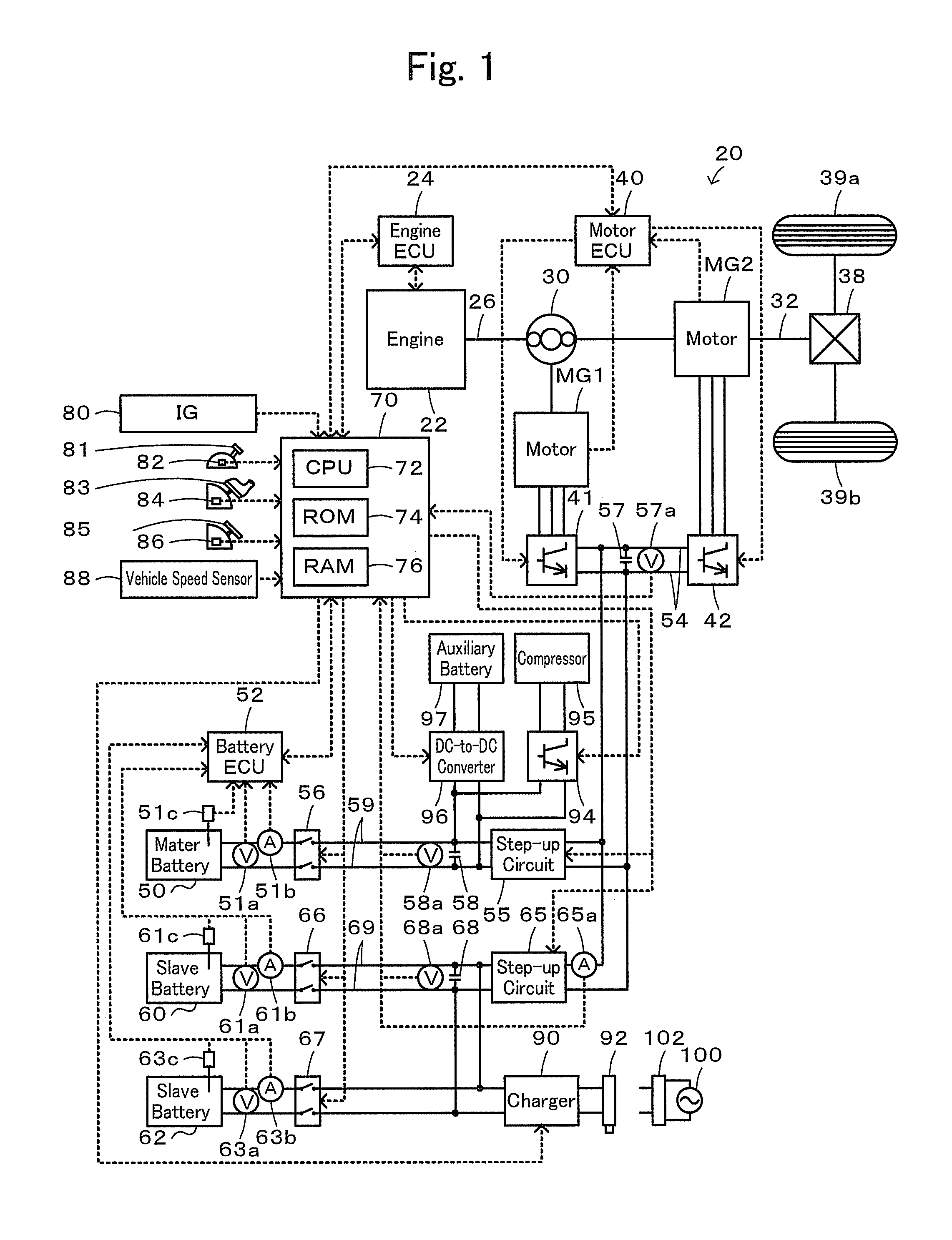
[0028]FIG. 1 schematically illustrates the configuration of a hybrid vehicle 20 in one embodiment according to the invention. As illustrated, the hybrid vehicle 20 of the embodiment includes an engine 22 that consumes a fuel such as gasoline or light oil, an engine electronic control unit (hereafter referred to as engine ECU) 24 that controls the engine 22, a planetary gear 30 that has a carrier connected to a crank shaft 26 of the engine 22 and a ring gear connected to driveshaft 32 linked to driving wheels 39a and 39b via a differential gear 38, a motor MG1 that is constructed as a synchronous motor generator and has a rotor connected to the sun gear of the planetary gear 30, a motor MG2 that is constructed as a synchronous motor generator and has a rotor connected to the driveshaft 32, inverters 41 and 42 each for driving the motors MG1 and MG2, a motor electronic control unit (hereafter re...


PUM


Abstract

In the case the gearshift position is the parking position at the state that the master battery is connected via the master side step-up circuit to the motor side and either of the two slave batteries is connected via the slave side step-up circuit to the motor side, the drive of both of the master side step-up circuit and the slave side step-up circuit is stopped. After then, in the case that the accumulated charge ratio difference obtained by subtracting the accumulated charge ratio of the master battery from the accumulated charge ratio of the slave battery connected to the motor side is less than the threshold value, the drive stop of both of the master side step-up circuit and the slave side step-up circuit is continued.

Description

TECHNICAL FIELD[0001]The present invention relates to an electric vehicle and a control method of an electric vehicle.BACKGROUND ART[0002]One proposed electric vehicle has a motor generator, an inverter that drives the motor generator, a first electric storage device, a first converter that performs voltage conversion between the first electric storage device and both of a main positive bus line and a main negative bus line connected to the inverter, the second electric storage device, and a second converter that performs voltage conversion between the second electric storage device and both of the main positive bus and the main negative bus line (see, for example, Patent Document 1). In this electric vehicle, a discharge power distribution ratio of the each storage device is calculated according to a ratio of remaining electric energy, where a current SOC reaches to a preset SOC that allowable discharge power is restricted, of each of the electric storage devices. A charge power di...

Claims


Application Information

Patent Timeline
Patent Type & Authority Applications(United States)
IPC IPC(8): B60L1/00B60L50/15B60L50/16
CPCB60K1/02Y02T90/14B60K6/442B60K6/48B60K6/52B60L1/003B60L11/123B60L11/14B60L11/1816B60L11/1853B60L11/1861B60L11/1868B60L2220/12B60L2220/14B60L2240/486B60W10/08B60W20/00B60W2510/244B60W2520/10B60W2540/10B60W2540/12B60W2540/16Y02T10/6217Y02T10/6221Y02T10/6234Y02T10/6265Y02T10/7005Y02T10/7044Y02T10/7066Y02T10/7077B60K6/365B60L50/16B60L50/61B60L53/14B60L58/12B60L58/18B60L58/20Y02T10/62Y02T10/70Y02T10/7072B60W10/28
Inventor KOMATSU, MASAYUKI
Owner TOYOTA JIDOSHA KK
Why Eureka
Try Eureka