This helps you quickly interpret patents by identifying the three key elements:
Problems solved by technology
Method used
Benefits of technology
Benefits of technology
[0021]The wireless communication device according to the present invention provides effects that as large a mounting area as possible can be secured for an antenna of one frequency band and an antenna of the other frequency band each, and that a communication range equal to the communication range of a tag for an LF-band RFID system (or an HF-band RFID system) alone and the communication range of a tag for a UHF-band RFID system alone, thereby being applicable to both the LF-band RFID system (or the HF-band RFID system).
Problems solved by technology
If this tag is used to manage the entrance / exit of vehicles, for example, the communication range is not quite sufficient and needs to be improved.
The tag thus has a problem in that a communication range sufficient for practical uses is not easily accomplished.
Method used
Image
Click on the blue label to locate the original text in one second.
Reading with bidirectional positioning of images and text.
Examples
first embodiment
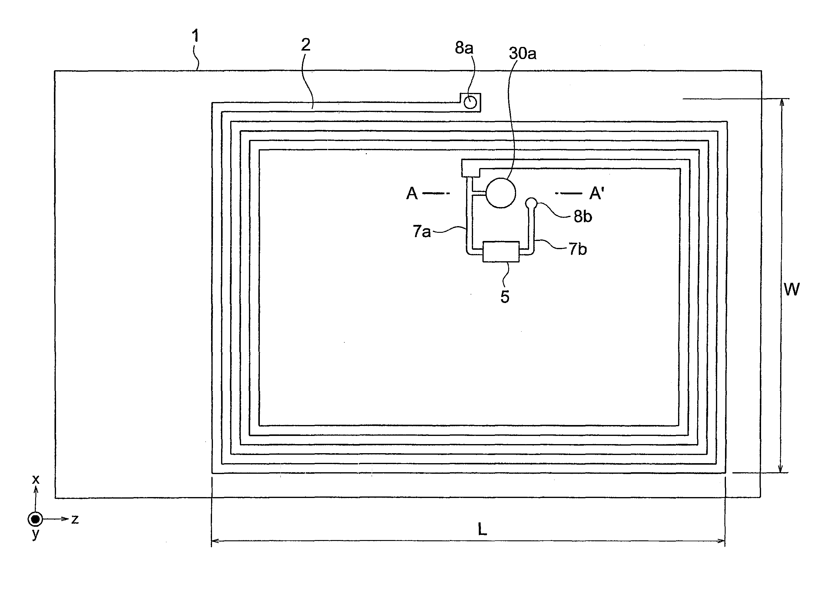
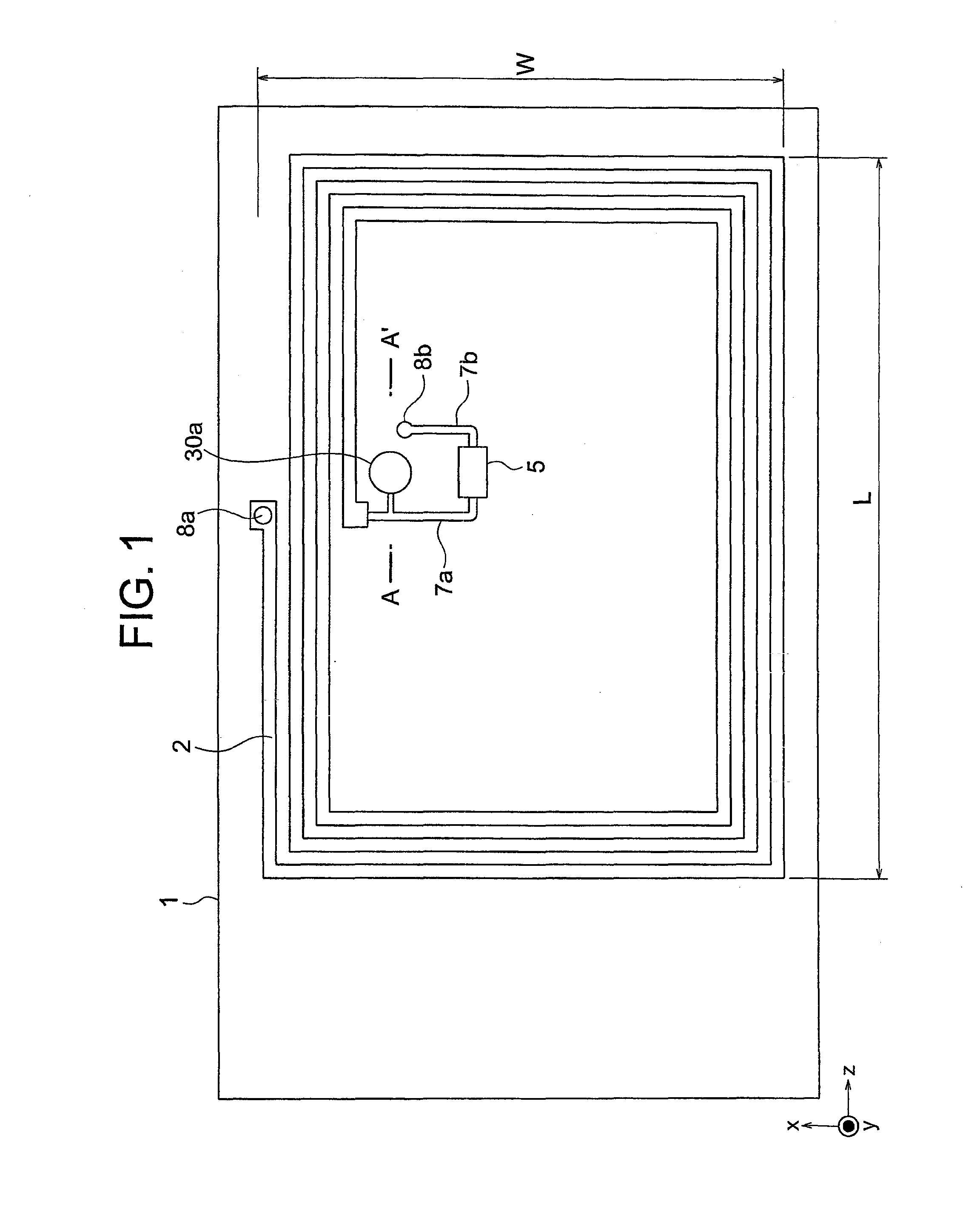
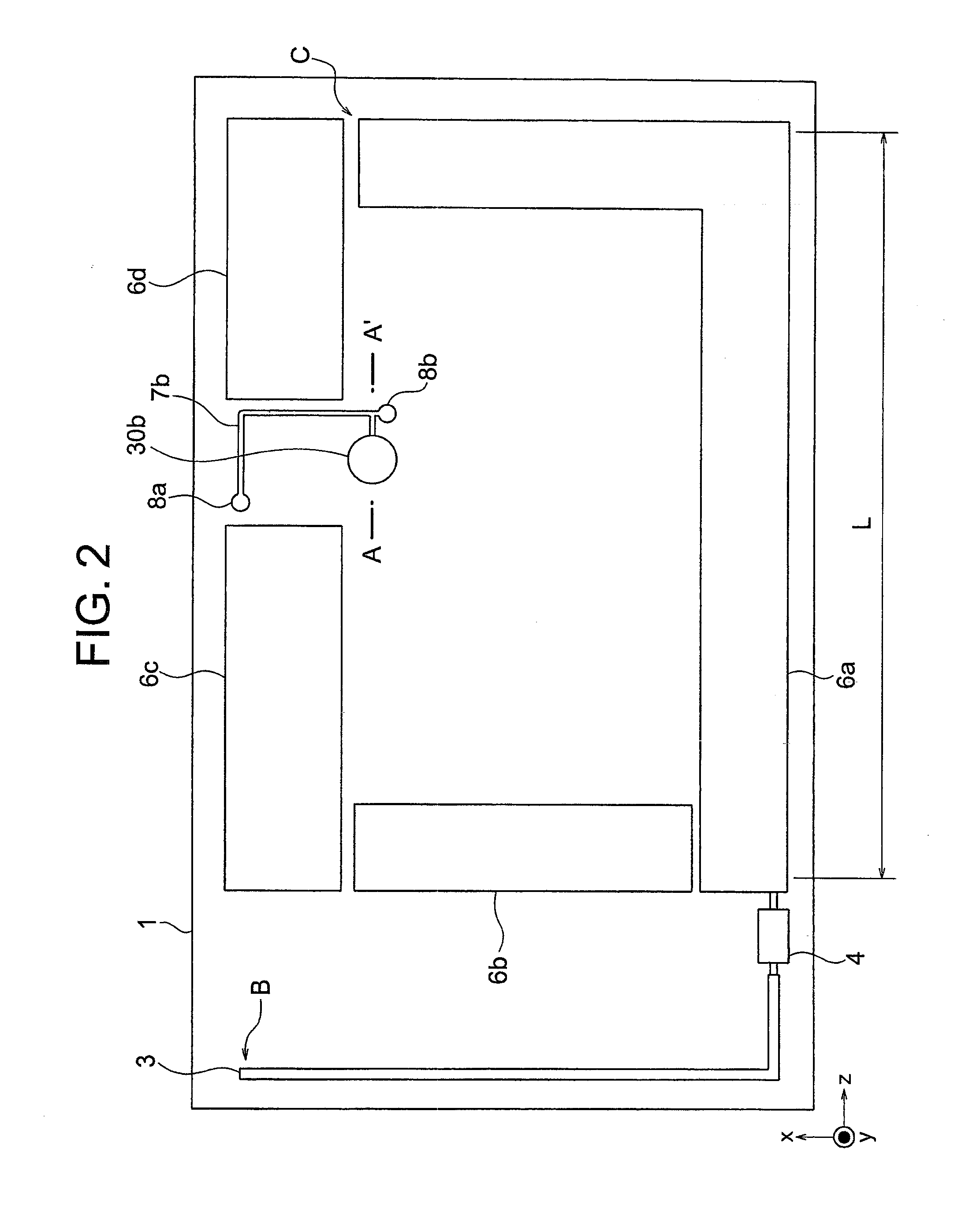
[0064]A wireless communication device according to the first embodiment of the present invention is described with reference to FIG. 1 to FIG. 14. FIG. 1, FIG. 2, and FIG. 3 are diagrams illustrating the structure of the wireless communication device according to the first embodiment of the present invention. In the following description, the same or equivalent components are denoted by the same reference symbols throughout the drawings.
[0065]FIG. 1 is a plan view illustrating the top structure of the card-type wireless communication device, FIG. 2 is a plan view illustrating the bottom structure of the card-type wireless communication device, and FIG. 3 is a sectional view taken along the line A-A′ of FIG. 1 and FIG. 2.
[0066]Referring to FIG. 1 to FIG. 3, the wireless communication device according to the first embodiment of the present invention is provided with a plate-like-object 1, which is a dielectric material , a magnetic material, or the like, a coiled conductive object 2, ...
second embodiment
[0115]A wireless communication device according to a second embodiment of the present invention is described with reference to FIG. 15 to FIG. 22. FIG. 15 and FIG. 16 are diagrams illustrating the structure of the wireless communication device according to the second embodiment of the present invention.
[0116]In order to enhance the communication performance in the second frequency band, it is basically preferred to give the coiled conductive object 2 a wide opening area. On the other hand, in order to enhance the communication performance in the first frequency band in the antenna structure of the first embodiment (FIG. 1 and FIG. 2, FIG. 9 and FIG. 10, and FIG. 12 and FIG. 13), it is desirable to place the conductive object 3 outside the coiled conductive object 2. Those are conflicting requirements and meeting both requirements is difficult. Specifically, in the first embodiment where the coiled conductive object 2 cannot have a maximum opening area within the plate-like object 1,...
third embodiment
[0129]A wireless communication device according to a third embodiment of the present invention is described-wish reference to FIG. 23 to FIG. 30. FIG. 23 and FIG. 24 are diagrams illustrating the structure of the wireless communication device according to the third embodiment of the present invention.
[0130]The first embodiment and the second embodiment require one integrated circuit for each frequency band, namely, the integrated circuit 4 which has functions necessary for communication in the first frequency band and the integrated circuit 5 which has functions necessary for communication in the second frequency band. In recent years, multi-frequency integrated circuits which have communication functions necessary for different frequency bands in combination are beginning to be put into practical use. This embodiment describes an antenna structure compatible with those multi-frequency integrated circuits.
[0131]FIG. 23 and FIG. 24 illustrate an antenna structure for using an integra...
PUM
Abstract
Provided is a wirelesscommunication device capable of communicating a signal in a first frequency band and a signal in a second frequency band, which is lower in frequency than the first frequency band, including: a plate-like object; a first integrated circuit which has a function of communicating in the first frequency band; a first conductive object which is connected to one of two input / output terminals of the first integrated circuit; a conductive object group constituted of a plurality of second conductive objects at least one of which is connected to another of the two input / output terminals of the first integrated circuit; a second integrated circuit which has a function of communicating in the second frequency band; and a coiled conductive object of which a winding start side is connected to one of two input / output terminals of the second integrated circuit and a winding end side is connected to another of the two input / output terminals of the second integrated circuit. The conductive object group and the coiled conductive object are formed on opposite faces of tile plate-like object from each other. In a perspective view from a normal line direction of the plate-like object, a half or more of the coiled conductive object overlaps with the conductive object group.
Description
TECHNICAL FIELD [0001]The present invention relates to a wirelesscommunication device that has the antenna structure of a tag used in a radio frequency identification (RFID) system, and more particularly, to a wirelesscommunication device capable of multi-frequency communication.BACKGROUND ART [0002]RFID systems for automatically recognizing and managing people or articles are rapidly becoming popular in recent years. The electromagnetic field emitted from an antenna for use in RFID systems contains three fields: a quasi electrostatic field, an induction field, and a radiation field. The intensities of those fields are in inverse proportion to the cube of the distance from the antenna, the square of the distance from the antenna, and the distance from the antenna, respectively.[0003]From this viewpoint, communication methods for RFID systems are roughly classified into an induction fieldcoupling method which uses an induction field in the LF band or the HF band and a radiation fi...
Claims
Application Information
Patent Timeline
Application Date:The date an application was filed.
Publication Date:The date a patent or application was officially published.
First Publication Date:The earliest publication date of a patent with the same application number.
Issue Date:Publication date of the patent grant document.
PCT Entry Date:The Entry date of PCT National Phase.
Estimated Expiry Date:The statutory expiry date of a patent right according to the Patent Law, and it is the longest term of protection that the patent right can achieve without the termination of the patent right due to other reasons(Term extension factor has been taken into account ).
Invalid Date:Actual expiry date is based on effective date or publication date of legal transaction data of invalid patent.

